Copper Clad Aluminum wire
- Ref Price:
-

- Loading Port:
- China Main Port
- Payment Terms:
- TT OR LC
- Min Order Qty:
- -
- Supply Capability:
- -
OKorder Service Pledge
OKorder Financial Service
You Might Also Like


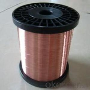
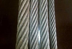
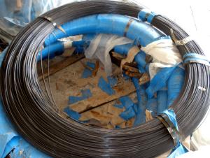
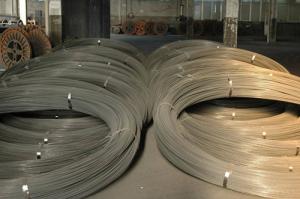
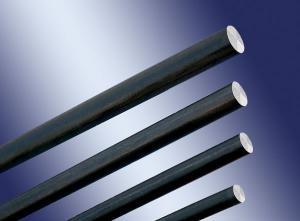
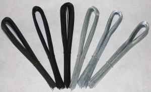
Copper Clad Aluminum is an electrical conductor which has an outer sleeve of copper metallurgically bonded to a solid aluminum core. The combination of these two metals make it uniquely suited to many electrical applications
Standard:
SJ/T 11223-2000 ASTM B 566-93
Feature:
Compared to copper conductors:
Higher Flexibility due to lower elastic modulus 63% material weight reduction due to lower specific gravity of CCA over regular copper
Compared to aluminum conductors:
Better corrosion resistance than aluminum due to copper layer Lower resistance due to high electric conductivity of copper Better Solderability Higher strength than aluminum
Application:
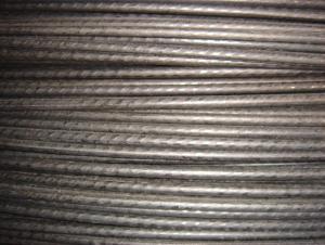
In high frequency signal transmission field, it is applied to: l Standard Material of Conductor in CATV Coaxial Cable; l 50 Ohm Radio Frequency Aerial; l Leaky Cable; l Soft Coaxial Radio Frequency Cable; l Data Cable
In power transmission field, it can be applied to: l Stranded wire; l Power Cable; l Control Cable; l automotive cable; l Building distribution wire; l Busbar; l Radio Frequency shielding;
In special electromagnetic wire, it can be applied to: l Coils in motor and fans, mahjong machine, Loudspeakers l Voice coils (e.g. in Headphone, Headset, ...) l Windings
Manufacture Scope:
0.12MM~5.50MM
Physical property of CCA wire
Characteristics of CCA wire
| |||||||||||||||||||||||||||||||||||||||||||||||||||||||||||||||||||||||||||||||||||||||||||||||||||||||||||||||||||||||||||||||||||||||||||||||||||||||||||||||||||||||||||||||||||||||||||||||||||||||||||||||||||||||||||||||||||||||||||||||||||||||||||||||||||||||||||||||||||||||||||||||||||||||||||||||||||||||||||||||||||||||||||||||||||||||||||||||||||||||||||||||||||||||||||||||||||||||||||||||||||||||||||||||||||||||||||||||||||||||||||||||||||||||||||||||||||||||||||||||||||||||||||||||||||||||||||||||||||||||||||||||||||||||||||||||||||||||||||||||||||||||||||||||||||||||||||||||||||||||||
- Q:Why does a thin wire melt and a thick wire glow when put up to the terminals? Explain in terms of resistance and current. Thanks=]
- the electrical restistance of a thin wire is greater that the tick wire. thus : Watt = current * current * resistance if the resistance of the thick wire is 10 times the resistcance of the thin wire , then ( with same voltage ) you have for small wire Watt = current * current * resistance for thick wire Watt = 10*current * 10*current * (resistance/10) = 10current current resistance. so the power generated in the thick wire is ten times more than the power in the thin wire ( if you keep the voltage the same ) so that is not why the smaller one melts. I dont know why it melts then, interesting
- Q:I have a question on Razer Naga Epic.Does the USB charger wire also act as a mouse signal wire or is it still a warless signal even if it's plugged in thru a wire?Bottom line, is the wire in the Razer Naga Epic only for charging?
- This Site Might Help You. RE: Razer Naga Epic mouse wire question.? I have a question on Razer Naga Epic. Does the USB charger wire also act as a mouse signal wire or is it still a warless signal even if it's plugged in thru a wire? Bottom line, is the wire in the Razer Naga Epic only for charging?
- Q:Just took off the starter on a cavalier and forgot to label the wires. Can someone please send me a diagram of where all these wires go, or just tell me where they go. there are big post and one small one. Please help asap. Thanks.
- all wiring with large eyelet end,s go to main solenoid terminal...the large brass/copper post in the center/top. the small wire/wire,s attach to the terminal marked with a S for solenoid. the small terminal to the side. do not place any ground wire,s to either terminal....best of luck.
- Q:My boat came with a rule 500 2-wire auto pump. I have an on/off switch at the console. My replacement has 3 wires. How do I connect the 3 wires and still use my on/off switch?
- It all depends on the function of the third wire. The instructions that came with the pump should tell you what it's for. If you're only using the pump with the switch you only need to apply 12V and a return to the pump. The switch could be in either leg, but will normally be in the +12V leg. The third wire could be an earth ground for safety or you might have a built in float switch so that you can apply 12V directly to that 3rd wire. When the internal float switch goes high enough it will turn on the bilge pump for you. Your best bet is still to read the instructions before you install it though...
- Q:Theirs a green ground wire, a white neutral wire and for some reason 3 black wires.
- If the ceiling fan has three speeds, those would be wired to a 3 position switch as low, medium and high. Normally the wires would be labeled if they use the same color. If they aren't tagged, and you want to put in a speed control switch, you'll need to experiment; either at the fixture, or just wire them down to the wall switch and make your temporary connections there to see which wires go with which speeds (then TAG them!).
- Q:Currently I have the two wires no ground wire and some two wire with ground outlets (upgrade some time before). Is it allowed in the NEC to run a separate ground wire from one of the two wire with ground outlet to the two wire outlet without changing the old wires?
- It isn't allowed to ground the new 'grounding' receptacle to another receptacle on another circuit (if that is what you are asking) Other than that, it IS allowed to be grounded to an accessible point on the grounding electrode system (metal cold water pipe or wire connected to it), the system grounding electrode (ground rod, etc.), the ground bar in the panel from which that circuit originates, or the grounded conductor bar in the panel which the circuit originates (neutral bar). The only other legal option is to install a GFI and label it No Equipment Ground. You can connect downstream receptacles to that same GFI, but cannot connect a ground wire from the GFI to any downstream receptacles and they too must be marked No Equipment Ground and GFCI Protected. The way a GFI works is quite simple. If the current on the hot and neutral conductors isn't the same (within 5mA), it trips. So if there is a different path from hot to anything other than neutral, it will trip.
- Q:Need to wire three ceiling fans in series
- Do noot wire them in series. Get a book on basic house wiring so you understand what the term means. Best solution is for you to hire a local qualified professional electrician to do the work. Probably less than a day work for a journeyman.
- Q:im installing an amp and i have no clue what to do with thw power wire.... I read to cut open my steros power wire (usually the blue) and wrap my power wire around it... I found the blue wire but there was a tag... Caution Remote output only... This is not the wire for power supply. please connect this wire to the remote for the amplifier... Does this mean i just connect this wire directly to my amp?
- ok wait hold up. so the only wire that should be hooked from the amp to the headunit is your speaker wires, remote turn on wire, and your rca cables. ....What you need to do is get the power cable(usually red) run it from positive on the battery to the POS on your amp. next put your ground wire from the GND on the amp to bare metal on your cars chasis.
- Q:I have a Trane Heat pump AC/Heat. There are several wires and Im a little stumped? There is a Tan wire*which the book does not show) and a black wire that is labled X1 on the old one but is not in the new ones book? I have also been told NOT TO hook blue wire up to the B port?? But if not, not sure where to put it?
- Go get an HVAC technician to install it. You'll have at lot less headaches
- Q:I have 2 wires that go from the Solenoid to the wiring harness. But i don't know which wires go to where. One of the wires from the Solenoid it the remote switch and the other is the power for my whole interior. There are red, orange and black wires that come from the wiring harness. but i don't know which ones to use.
- I would say you should have a wiring schematic to guide you. You could try searching on line for some free information or buy a shop manual published by Chevrolet. You could try one of the Haynes manuals, but sometimes they are not as complete as the shop manuals. You could also go to a local dealer and speak with someone in the Parts Dept. or speak with a mechanic. If you want to try it yourself, I would have someone hold the key in start position, and measure the voltage on those three wires on the wiring harness. Only one should have voltage when the key is in the start position. This wire has to go to the solenoid. That's the next thing to determine, which one. One is probably a ground and one goes to the coil in the solenoid. With an ohm meter, measure the resistance on these two wires. The one with the most resistance is probably the ground, and the other one is probably the coil. If you connect this wire to the wire we mentioned earlier, you will probably be OK. After this point, I don't think you could hurt anything. If you try it and it won't work, switch wires. Good luck.
1. Manufacturer Overview |
|
|---|---|
| Location | |
| Year Established | |
| Annual Output Value | |
| Main Markets | |
| Company Certifications | |
2. Manufacturer Certificates |
|
|---|---|
| a) Certification Name | |
| Range | |
| Reference | |
| Validity Period | |
3. Manufacturer Capability |
|
|---|---|
| a)Trade Capacity | |
| Nearest Port | |
| Export Percentage | |
| No.of Employees in Trade Department | |
| Language Spoken: | |
| b)Factory Information | |
| Factory Size: | |
| No. of Production Lines | |
| Contract Manufacturing | |
| Product Price Range | |
Send your message to us
Copper Clad Aluminum wire
- Ref Price:
-
- Loading Port:
- China Main Port
- Payment Terms:
- TT OR LC
- Min Order Qty:
- -
- Supply Capability:
- -
OKorder Service Pledge
OKorder Financial Service
Similar products
New products
Hot products

Hot Searches
Related keywords

