
Tinned Copper Clad Steel Wire ( Tinned CCS wire )
- Ref Price:
-

- Loading Port:
- China Main Port
- Payment Terms:
- TT or LC
- Min Order Qty:
- -
- Supply Capability:
- -
OKorder Service Pledge
OKorder Financial Service
You Might Also Like


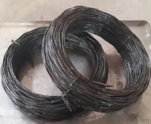
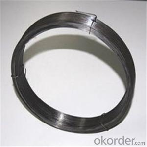
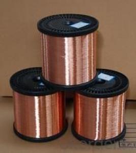
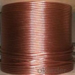
1.Product Description:
CCS wire is we common named “CP” wire , which is made of high-class and low-Carbon steel , clad non-oxygenic copper layer by mechanical method, than plating Tin. Due to the high purity of layer, the copper core and tin layer cladding close-grained .
Tinned CCS wire with the high conductivity & magneto conductivity of Copper high strength of steel , bending and tin’s thermal conductivity, corrosion resistance , and oxidation resistance at high temperatures . since its superior strength and weldability , resistance to bending, welding point firmly , its anti-vibration up to 3-6 times compare with pure copper wire , easy to automate
2. Product Characteristic:
This wire is widely used for lead wire & jumper wire of electronic components, core of RF cable, it has become a perfect wire of communication, electronics , electric power industry .
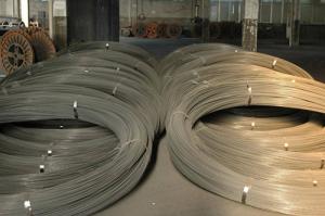
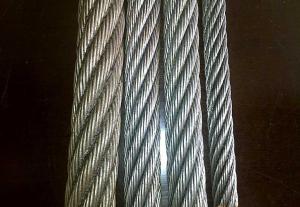
3.Specification :
Diameter: 0.08mm--2.5mm
Spool size:DIN100mm, DIN130mm, DIN180mm, DIN250mm, DIN400mm,
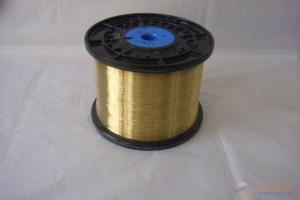
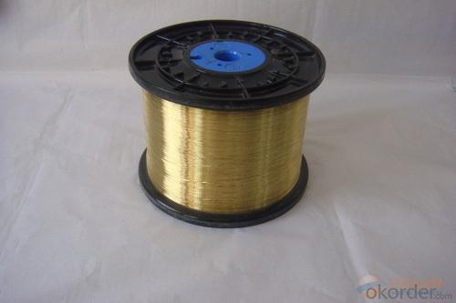
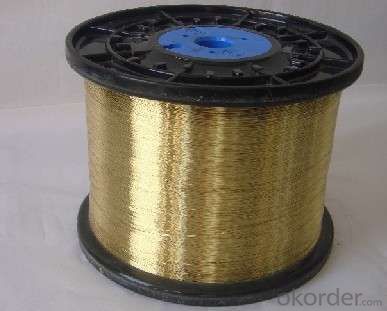
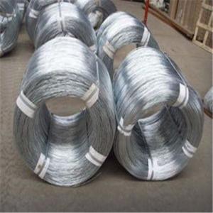
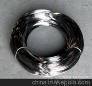
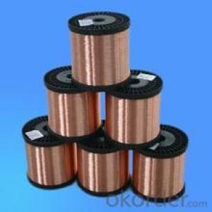
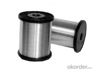
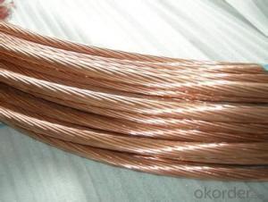
4. Reference Picture:
")
")
")
- Q: Source 115V 20A breakerI have 12/2 wire and want to wire this:GFCI 15A receptacle -to- 15A receptacle -to- 15A receptacleI have basic wiring skills, just need reassurance. Thanks.
- Comment: I don't know why john said to use a 6 piece of wire and wire nut the blacks together. Why not use the screws provided for wiring through? Why go through the trouble of making a pigtail ? Edit; I stand corrected.
- Q: the fused ignition wire and illumination wire, i cant figure out where they go on a Dual stereo system model1225 Help. ( on a 1990 ranger )
- the ignition wire is going to be a yellow with a black stripe(car wire) and the instruction manual will tell you for the head unit illumination wire i just taped up since my head unit didnt require it =) like they say...if it turns on it dont need it
- Q: i want to rewire my trailer harness on my truck. i have a 6 wire roung plug but i wat a 7 wire plug. what is the 7 wires for?
- Prepare for accurate and confusing information. The center pin on a 7 pin plug is generally used for backup lights (black wire) if you have them wired in. Being that you have a 6 pin plug you probably don't so you will disregard the center pole. This is the order of color starting from the ground pole (white wire). The ground pole should be the one next to the slot in the body of the plug that lines it up with the plug housing when you put it all together. White (ground), Yellow (L turn), Brown (tail lights), Red (battery charge wire), Green (R turn), Blue (trailer brakes). If you don't have trailer brakes, disregard that pole. The brake lights work through the turn signals, if they are wired separately, it is wrong. Starting at the ground pole next to the slot in the plug, the order of colors goes around the plug in the direction away from the slot, you will end with the blue wire on the other side of the slot next to the white wire. It's very confusing to explain and when you read the colors on the plug compared to what I have told you, you will definately scratch your head. This is the (U.S.) national standard for all trailer wiring, unfortunalely, not all manufacturers adhere to this thus causing confusion for people such as yourself. I cannot even begin to guess how many trailers I have wired and how many tow packages I have installed on cars and trucks. I wish there was an easier way to explain it but the only other option is a diagram which answers does not support. Worse comes to worse and you don't like any of the other answers you get, e-mail me and I will mail you a diagram or maybe even a picture if I can come up with one.
- Q: Peugeot Speedfight 2, How can i find out what colour wire is fuel? indicators? .. Would it all be shown on the wiring diagram?
- most bikes use the same wiring system... 50% anyway Black=Common Negative Red= Ignition Positive Grey= Ignition Kill Black+White=Ignition Kill (Ground) Green+Yellow=Ground Yellow= left indicator Yellow + Stripe= right indicator I recommend going on OKorder and asking a seller offering bike alarms for a wiring diagram for your bike, they will have them 99% of the time (it would be wrong if i sugested you tell them you bought an alarm from them in the past... as a reason for them to e-mail you a diagram - dont do that ;-) cgi.OKorder .uk/CYCLONE-MOTORBIKE-...
- Q: do you match positives and negatives or positives and positives when wiring a car stereo
- This Site Might Help You. RE: color code for wires in a 2000 ford explorer? do you match positives and negatives or positives and positives when wiring a car stereo
- Q: i just got guitar hero 3 and i want to buy another guitar contoller for the xbox 360 but my mom only wants to buy the wired one because it is cheaper is there anything wrong with the wired one and should i get it or not since i will be playing it with my brother. also how long will the wire be.
- OK don't laff. i have gh3 and a wired and a wireless guitar. the cord is about 6 feet long and it is ok. there is nothing worse than being about half way through a song and your 360 says please reconnect controller. go for the wired and rock on!
- Q: A wire has a resistance of 21.0 ohms. It is melted down, and from the same volume of metal a new wire is made that is three times longer than the original wire. What is the resistance of the new wire?
- The resistance of the new wire is (in terms of its length, area resistivity); R2 = pL2/A2 And the resistance of the original wire is; R1 = pL1/A1 The ratio is;(resistivity will cancel because its the same for both situations) R2/R1 = L2A1/L1A2 given L2 = 3L1 R2/R1 = 3A1/A2 To find the new cross-sectional area ,require the volumes to be equal; L2A2 = L1A1 3L1A2 = L1A1 A2 = (1/3)A1 Sub this into the R2/R1 equation to get; R2/R1 = 9 R2 = 9R1 = (9)(21) = 189 ohms
- Q: To help clean things up and make wiring a little more simpler on my jeep i got a fuse/relay box off an old junk car. i want to wire my off road lights into this relay box but i'm not sure what size wire is in the box it appears to be either 18 or 16 AWG one place said to strip the wire and measure the wire another says measure in the insulation. i'm not sure what to do. but if it is 18 awg would it hurt to go to a bigger size after the fuse box to my lights or should i rewire the whole box?
- For okorder /... Wiring gauge always specifies the diameter of the WIRING not the insulation, since the insulation thickness can vary. You would have to strip the wire and measure the bare wire with a gauge. You can also look at the printing on the insulation for the gauge. Look for something like AWG 14 etc. You can buy a standalone headlight harness that contains the relay and wiring for aftermarket lights. I would recommend running both positive and negative wires all the way to the battery for maximum current.
- Q: the sensor part has 4 wires,(2 white,1 black and 1 red)each light has 1bl.and 1white
- The other answer that has directions doesn't sound right for your case. Do you have a link to the actual product? Two white wires sounds strange, unless they have stripes or something to differentiate them. It seems pointless to have 2 wires that would just be connected together. Give me a link or the actual brand/model number and I'll give more information.
- Q: pendant wiring hookup. issue: light is always on house wires: red, white, black, ground pendant wires: green, white, black (and a ground wire to the frame) I did connect red to green, white to white, black to black, ground to ground is connecting the red to green the problem causing the light to be always on? do I just disconnect the red to green to fix?
- First of all you need to determine where the switch that controls the box on the ceiling is. It sounds to me as though three conductor wire was used in the event that a ceiling fan might be installed at some future date. Turn off the breaker to that circuit first. Make sure it is off with a circuit tester. Remove the plate from the switch location and unscrew and pull out the switch. There will be a pair of wires ( white black and bare ground ) coming in to the box. This is where power is coming from. There will also be a trio of wires ( black, red and white plus bare ground. Which ever wire from the trio is attached to the switch will determine which hot wire to connect to in the ceiling box. You will attach that to the black wire from the fixture, the white to white and the green to bare ground. If there are two switches in the same box on the wall, choose the one closest to the door, determine wire color, cap the other color wire in the ceiling box with a wire nut and some electrical tape around it. Push it up in to the box first before any of the other wires. Then make the other connections, attach the pendant base to the ceiling box and you're done.
Send your message to us
Tinned Copper Clad Steel Wire ( Tinned CCS wire )
- Ref Price:
-
- Loading Port:
- China Main Port
- Payment Terms:
- TT or LC
- Min Order Qty:
- -
- Supply Capability:
- -
OKorder Service Pledge
OKorder Financial Service
Similar products

Hot products


Hot Searches
Related keywords

