
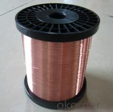
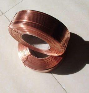
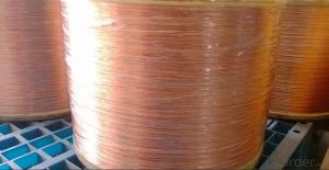
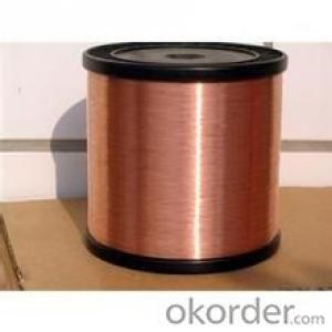
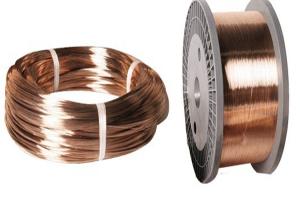
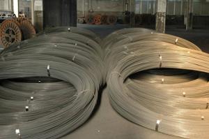
Copper Clad Aluminum wire
- Ref Price:
-

- Loading Port:
- China Main Port
- Payment Terms:
- TT OR LC
- Min Order Qty:
- -
- Supply Capability:
- -
OKorder Service Pledge
OKorder Financial Service
You Might Also Like


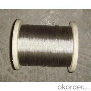

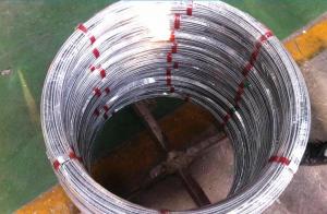
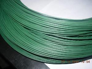
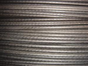
Copper Clad Aluminum is an electrical conductor which has an outer sleeve of copper metallurgically bonded to a solid aluminum core. The combination of these two metals make it uniquely suited to many electrical applications
Standard:
SJ/T 11223-2000 ASTM B 566-93
Feature:
Compared to copper conductors:
Higher Flexibility due to lower elastic modulus 63% material weight reduction due to lower specific gravity of CCA over regular copper
Compared to aluminum conductors:
Better corrosion resistance than aluminum due to copper layer Lower resistance due to high electric conductivity of copper Better Solderability Higher strength than aluminum
Application:
In high frequency signal transmission field, it is applied to: l Standard Material of Conductor in CATV Coaxial Cable; l 50 Ohm Radio Frequency Aerial; l Leaky Cable; l Soft Coaxial Radio Frequency Cable; l Data Cable
In power transmission field, it can be applied to: l Stranded wire; l Power Cable; l Control Cable; l automotive cable; l Building distribution wire; l Busbar; l Radio Frequency shielding;
In special electromagnetic wire, it can be applied to: l Coils in motor and fans, mahjong machine, Loudspeakers l Voice coils (e.g. in Headphone, Headset, ...) l Windings
Manufacture Scope:
0.12MM~5.50MM
Physical property of CCA wire
Characteristics of CCA wire
| |||||||||||||||||||||||||||||||||||||||||||||||||||||||||||||||||||||||||||||||||||||||||||||||||||||||||||||||||||||||||||||||||||||||||||||||||||||||||||||||||||||||||||||||||||||||||||||||||||||||||||||||||||||||||||||||||||||||||||||||||||||||||||||||||||||||||||||||||||||||||||||||||||||||||||||||||||||||||||||||||||||||||||||||||||||||||||||||||||||||||||||||||||||||||||||||||||||||||||||||||||||||||||||||||||||||||||||||||||||||||||||||||||||||||||||||||||||||||||||||||||||||||||||||||||||||||||||||||||||||||||||||||||||||||||||||||||||||||||||||||||||||||||||||||||||||||||||||||||||||||
- Q: I wired an outdoor lamp-post. I tested it before wiring it to the fuse box...and if I touch the lamp-post I feel the current (a slight shock). I will be using a ground fault breaker....so I assume if I wire it to that I am going to loose the connection. Any thoughts on what is wrong?
- In addition to the answer Paul gave, check the wiring that the white wire is the neutral or common wire and that it goes to the shell side of the lamp holder. A few years ago, I had a similar problem, when all of the checks were made, the panel was wired with the black wires on the neutral buss. Hence all of the devices were wired backwards. Call a qualified professional electrician to do the work.
- Q: at least 3 examples for wire and wireless......
- Wire simplex: Serial data from GPS to PC or autopilot using 2 wires. Wire, half duplex: Theatrical intercom, with push to talk buttons for each spotlight operator. Wire, full duplex: telephone. Wireless, simplex: infrared remote control for TV. Wireless, half duplex: walkie-talkie, family radio service, cb radio. Wireless, full duplex cellphone, cordless phone.
- Q: Ceiling lights wire guage
- It may depend on whether you are connecting to an existing circuit or you are running an entirely new one from your panel. If you are connecting to existing circuitry, then you need to check the breaker size. If it is a 15 amp circuit, then #14 is acceptable. If it is a 20 amp, then you must use at least #12. It is very unlikely that you are required to use #10. NEC does not require it for a 20 amp circuit. If you are running a new circuit, then you have your choice. Just make sure that the breaker sizes and wire sizes match as described above. Contrary to the advice of some, it is just fine to run a 15 amp / #14 circuit for lights. The key is to avoid overloading the circuit. If you are just going to add a couple of fixtures, then the 15 amp will be fine. If you are adding 20 recessed can fixtures, you might consider the 20 amp circuit option. If you think that you are going to add more to the new circuit later, consider that when you decide which size to use. The difference comes in working with the wire. #14 is much easier to bend and work with. I certainly would not attempt to use #10 unless you actually do have some weird local codes that require it.
- Q: hey im wiring up a headunit to my L300 van. The factory headunit wasnt there and im having trouble connecting which colour wires to the factory colour wires. if anyone knows which coulours go to what would be much appreciatedcheers.
- Hi does anyone knows where the stereo looms connect back to .i.e. fused?
- Q: chicken wire mesh
- you live near a river it will make one fine fish trap round or oval 2 feet in dia.and 4 feet long .let me know and I will tell you how to naturaly bait the trap
- Q: I removed a dishwasher and now the wires are exposed. I turned off the circuit to that outlet. I am planning on waiting a while to replace the dishwasher. I want to turn the circuit back on so I can use the other outlets, but don't want to leave the wires exposed. Any ideas?
- N.E.C. code requires the wires to be placed in a box with a blank plate. use wire-nuts or black tape on the wires
- Q: Ok, bought this mower at an estate auction for next to nothing. It looks like its never been used. Previous owner ripped out all the wires to the ignition switch so it wouldn't sell I guess. It's the craftsman lt 1500. Model number 247.288812. It has the 17.5hp bs motor in it. Does anyone know the correct way the wires go to the switch? There are 3 red wires so its a bit unlike what im used to. Thanks in advance!
- On my sears mower with an electric clutch the switch is wired like this. G terminal is a black wire to ground. B terminal is a red wire to the ammeter. S terminal is a white wire to a safety switch. M terminal has two black wires one to the ignition coil and the other to a safety switch. L teminal is a red wire to the alternator and a red wire to the PTO switch.
- Q: My house is currently wired using Cat-5 lines. If I were to replace the Cat-5 wiring with Cat-6 wiring, would I see an increase in my DSL speed?
- you have to have speical equipment to use cat-6, so no if you did that it would still be the same as using cat-6
- Q: Okay so my question is how would I wire these in a ported box with 2 terminals on each side of the box? Also, is the quot;Bridged Wirefeatured in the diagram negative speaker wire? Thanks.
- It's a misnomer to use the term bridged in wiring subs. They should call it a jumper wire, or something similar. It's a minor detail, but it leads to novices thinking bridging is something done with subs -- it's not, it's the amp. Although since mono amps are becoming more and more common bridging is becoming a thing of the past as mono amps aren't bridgeable. The way I would do it would be to wire each sub to its respective terminal with the coils in series for 4 ohms.
- Q: Why is the current limiting circuit used to measure the resistance of wire by voltammetry?
- Because the resistance of wire is very small, almost zero. According to the current, equal to the voltage divided by the resistor, it is known that the resistance is almost an hour and the current is close to infinity. This will burn out the power supply, so the current limiting method must be used
Send your message to us
Copper Clad Aluminum wire
- Ref Price:
-
- Loading Port:
- China Main Port
- Payment Terms:
- TT OR LC
- Min Order Qty:
- -
- Supply Capability:
- -
OKorder Service Pledge
OKorder Financial Service
Similar products

Hot products

Hot Searches
Related keywords

