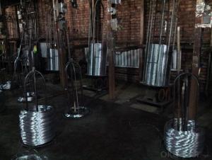
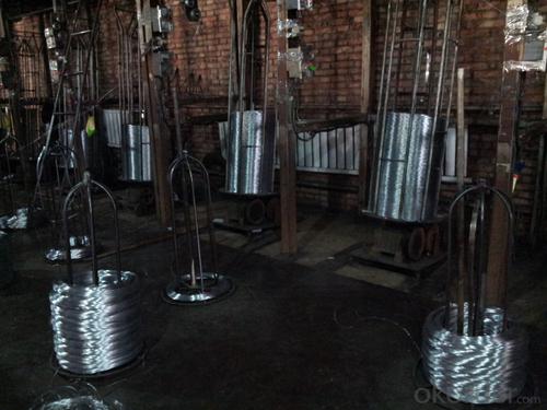
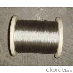
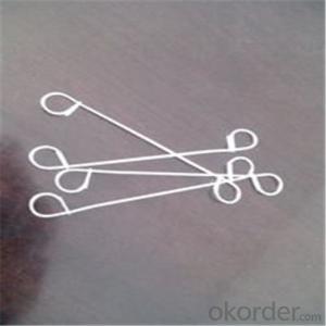
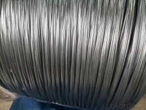
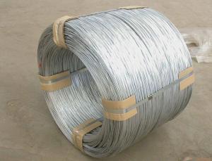
Hot Dip Galvanized Steel Wire For Razor Wire
- Ref Price:
-

- Loading Port:
- China Main Port
- Payment Terms:
- TT OR LC
- Min Order Qty:
- -
- Supply Capability:
- -
OKorder Service Pledge
OKorder Financial Service
You Might Also Like


Commercial Galvanised Steel Wire
(1) Quality : Meet GB/T 343 standard and other requirements of relevant standards .
(2) Zinc Coating: Meet GB/T 15393 standard and other requirements of relevant standards .
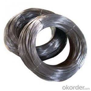
(3) Raw Material : Wire rod ——1006 , 1008 , 1018 , Q195 , etc, and zinc with 99.995% purity.
(4) Tensile Strength Range
Size (mm) | Tensile Strength (mpa) |
0.15-1.60 | 290-550 |
0.65-1.60 | 400-550 |
1.61-6.00 | 400-1200 |
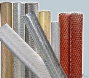
(5) Application : Used in wire mesh , artware , metal hose , binding for agriculture and construction , etc.
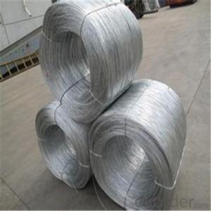
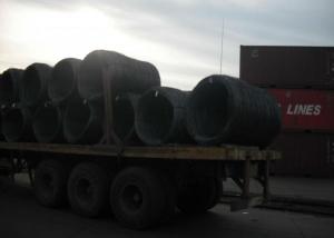
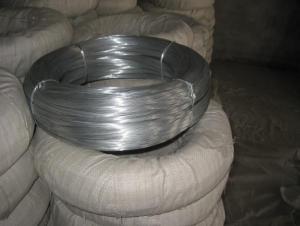
(6) Packing
Size (mm) | Coil Size | Spool Packing | Big Coil Packing | |
ID (mm) | OD (mm) | |||
0.15-0.26 | 6 inch | 1-14kg/spool |
|
|
0.27-0.60 | 8 inch | 1-100kg/spool |
|
|
0.61-1.60 | 12/14/16 inch | 1-100kg/spool | 250-400 | 400-770 |
1.61-6.00 |
| 14-500kg/spool | 450 | 800 |
508 | 840 | |||
(7) Zinc Coating
Meet GB/T 15393 standard.
Size (mm) | Weight of Zinc-Coating ( g/m2 ) | |||||||
A | AB | B | C | D | E | F | ||
A1 | B2 |
|
|
|
|
|
| |
≤0.25 |
|
| 30 | 20 | 18 |
|
|
|
>0.25-0.40 |
|
|
| 30 | 25 | 20 |
|
|
>0.40-0.50 |
|
|
|
| 30 | 20 |
|
|
>0.50-0.60 |
|
|
|
| 35 | 20 |
|
|
>0.60-0.80 | 120 | 110 |
|
| 40 | 20 |
|
|
>0.80-1.00 | 150 | 130 |
|
| 45 | 25 |
|
|
>1.00-1.20 | 180 | 150 |
|
| 50 | 25 |
|
|
>1.20-1.40 | 200 | 160 |
|
| 50 | 25 |
|
|
>1.40-1.60 | 220 | 180 |
|
| 50 | 35 | 30 |
|
>1.60-1.80 | 220 | 180 |
|
| 70 | 40 | 30 |
|
>1.80-2.20 | 230 | 200 |
|
| 80 | 50 | 40 |
|
>2.20-2.50 | 240 | 210 |
|
| 80 | 55 | 40 |
|
>2.50-3.00 | 250 | 230 |
|
| 90 | 70 | 45 |
|
>3.00-4.00 | 270 | 250 |
|
| 100 | 85 | 60 | 30 |
>4.00-5.20 | 290 | 270 |
|
| 110 | 95 | 70 | 40 |
>5.20-6.00 | 290 | 270 | 245 |
| 110 | 100 | 80 | 50 |
- Q: I'm replacing the door speakers in a 2001 Coupe Camaro with the factory sound system. I needed to know which wire was positive and which was negative so I bought a circuit tester. However, I keep getting the reading that both wires are positive. What could be causing this? I know the circuit tester works because I tested it on the battery terminals and it worked fine.
- 1 end goes on the negative post of the battery and the other end goes on any ground. some are grounded on the alternator bracket.
- Q: Got a new kenwood stereo to replace the old kenwood one in my VW polo 1998. Workes fine but when I pushed the stereo into my dashboard a wire came out so I pulled it out and put it back in. It worked, but next morning my car battery was near dead, I unplugged the stereo and its fine now. I assume I used wrong wire? Does anyone have a diagram or picture of how it should be wired?
- When you wired it did you butcher the wires or use a wiring harness? With the wiring harness, everything is labeled and color coded. Match colors to the kenwood wiring harness, splice or use butt connectors, plug harness into factory harness and player, attach antenna wire and you're done! If you did butcher the wires and left enough wire, repair the harness and buy a harness kit at your local sound shop, really cheap too! Good luck!
- Q: I have a new light fixture I am trying to install. The electrical box has two sets of black and white wires coming in. Both of the black wires are connected together while the white wires from either set were used to connect the old fixture. How should I wire in the new fixture. The switch for this light has only one set of black and white wires connected to the light switch.
- Possibly the box was wired using 2-conductor romex as a switch leg. That means one of the blacks is the power into the fixture box. It connects to the other black that goes to the switch. From the switch, the white is used to feed power back to the fixture. Hence you have one white that is neutral and one that is energized. This is not your fault but is 100% wrong, against code and is dangerous for someone like you that is trying to figure out what was done. Switch legs are accomplished using three conductors; one red, one black and one white. Use a current tester and see if you have one white that is hot and one that is neutral. If so, use a black magic marker and color the hot white one black. Do the same where it attaches to the switch.
- Q: Where is itI have a 1996 Honda Accord with a pioneer deh-p6400 head unit. I tried to install an amp. Held the ground to soem metal and tried to get it to turn on. I tried the power antennae wire and it didnt' work. Nothing seems to work. I dont want to splice any wires or anything
- hes right....all u have to do is continue the blue/white wire to the remote spot of the amp.
- Q: I know that a fuse is connected to the live wire. And I was wondering; since a fuse and the circuit breaker are similar, would the circuit breaker also be placed so that both terminals of the circuit breaker are connected to the live wire? If not, would it be connected to a wire that connects a live wire and neutral wire?
- The neutral wire is never connected to to a circuit breaker or fuse. It measures the current passing through the hot wire and opens if the current gets to high. Although the same amount of current passes through the neutral wire, an open breaker or fuse in that wire would let the load be connected to the hot wire but not to ground so you could bet shocked from it.
- Q: I have a copper colored wire, a black wire, a red wire and white wire in the little box in the wall?? please help.
- Heres okorder /... I hope this hleps.
- Q: I'm just wondering would i be able to connect a split 8 gauge wire with wire nuts like i'll explain:Use two wire nuts instead of one and divide the copper wire on both ends and wire nut both sides together with 2 nuts. The whole apparatus would look kinda like this:----lt;gt;---- with the wire nuts connecting the two arrow thingsThanks anyone
- 8 gauge wire is fairly heavy so I'll assume that this is not a low power application such as speaker drivers. I assume you want to do this because you don't have a proper connecting method of adequate size and you do have a couple of smaller size wire nuts. The proposed configuration would not be acceptable by any electric code for utility wiring for this reason. If one of those wire nut connections should fail, say due to corrosion or mechanical damage, the remaining connection would be required to carry the entire current load that both would normally share. This would no longer be adequately protected by a circuit breaker sized for the full 8 gauge wire. A high resistance point is developed with a high fire risk. Also the wire nuts would not be able to shield the conductors beyond the end of the wire insulation sheath. The exposed wire portions would need additional protection from incidental contact by some future service person. Please don't do this. Not a good practice.
- Q: Hello, I couldnt find a more appropriate category for this question, so i'm hoping someone here knows a little about wiring. today my booster fan burnt out, so I had to replace it. I got a 6in-line duct fan from the home depot. When I got home and took it out of the box, there is just wires with no plug on it. I have an old lamp that I took the cord off of, but there is only 2 cords, pos neg. The new fan has 3. white, black, and green. the black is the hot wire, and the green is grounded to the metal of the fan, and the white I am not sure of. I just want to know how to wire this plug to this new fan. if anyone knows how to do this please get back to me. Any help will be greatly appreciated. once again thank you.
- As you say, the black wire is hot and the green wire is ground. The white wire is called neutral. It's the return path for the voltage from the hot wire. Connect the black and white wires to the two power wires in your duct. Hopefully the colors are the same. The hot wire in the duct may be a different color, red or something. Colors like this are frequently used to mean a hot wire that's switched. It sounds like there's a plug for the fan. You can wire on a 3 pin plug and use an adaptor to plug it into a 2 pin outlet or just wire on a 2 bladed plug and leave the green wire off. Make sure it can't touch anything and cause a short.
- Q: What causes signal Loss and Distortion in Copper Wire?
- the resistance of the wire itself can be responsible for signal loss. electromagnetic fields may cause distortion. Another possibility is if the signal is not terminated properly you may experience a reflection of the signal traveling in opposition of the desired signal. Heat can cause loss or distortion. corrosion on the copper wire may also cause loss or distortion of the signal.
- Q: Whenever I'm making jewelry, I typically wind up using crimp beads (with toggle closures, in most cases). Whenever I cut off the beading wire at the end, after enclosing the crimp bead around it, there's always this itsy bitsy part of the wire that irritates me to no end when I wear the jewelry. It seems that I can only cut the wire so much before I wind up snipping at the crimp bead. How can I remedy the irritation fact of the left-over wire?Maybe put glue on the wire piece and let it dry? Idk. Grr.
- Depending on the size of the hole in the beads, I usually run the wire down throw about 2 inches worth of beads; then crimp and clip. This also ensures that if the necklace if caught and pulled you have about 2 inches of slack before you are chasing beads on the floor. If you hole in the beads are small you can do two different things. 1) find a coordinating bead with larger holes that you can end the necklace with on both sides of the catch 2) Be sure your wire is running straight back down the original wire after going through the crimp, then crimp and clip.The end of the wire will be straighter and not tend to go out to the side and punch your neck. And unfortunately there is not a solution every time.
Send your message to us
Hot Dip Galvanized Steel Wire For Razor Wire
- Ref Price:
-
- Loading Port:
- China Main Port
- Payment Terms:
- TT OR LC
- Min Order Qty:
- -
- Supply Capability:
- -
OKorder Service Pledge
OKorder Financial Service
Similar products


Hot products


Hot Searches
Related keywords

