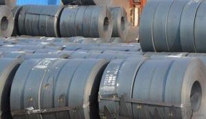
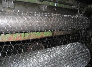
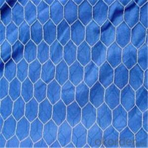
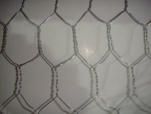
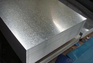
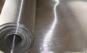
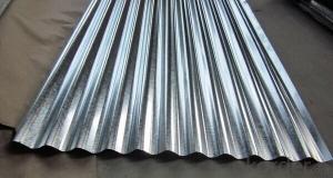
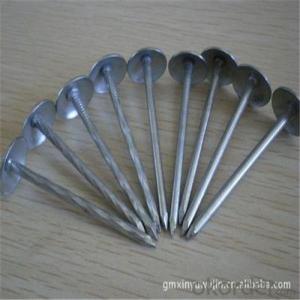
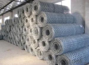
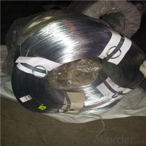
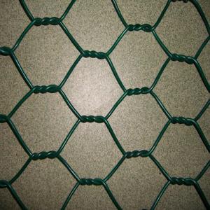
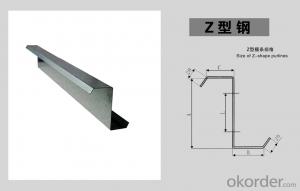
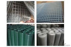
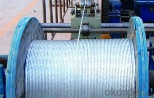
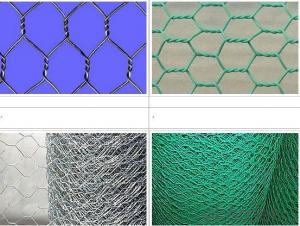
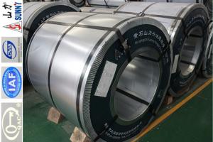
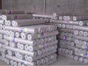
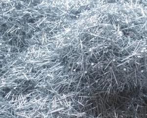
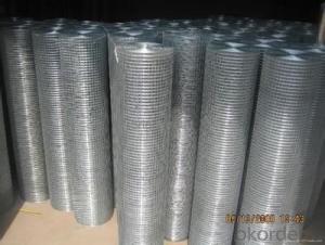
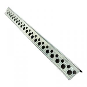
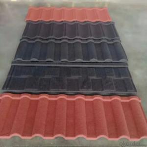
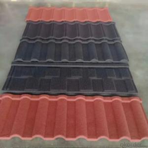
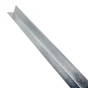
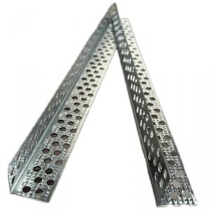
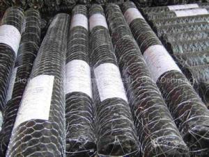
Galvanized Steel Stucco Netting

Hot Products
FAQ

My dog chewed the wiring and i dont know how to re-connect
Lets see, if your dog chewed the wires, he probably did it right at the valves. Here's what you do (depending on how many valves you have) 1. Each valve solenoid has 2 wires coming out of it. Grab one (of the 2- it doesn't matter which) wire from each valve and twist them together. Call this the COMMON wire (usually white). 2. Go to the clock/timer/controller and look to see where the wires are connected. Check to see which color wire is deginated as the COMMON wire (or doesn't have a station number designation) 3. Once you find out which wie is the common, go back to the valves and twist this wire onto your BUNDLE with a wire nut. 4. Connect the remaining wires at each valve to any corresponding wire (on the other end). Make sure that you eventually solidify these connections with waterproof wire connectors. 5. Check the stations at the clock, running individual stations and making sure the correct run-times correspond to the valve assignments- adjust or flip wires at the clock instead of switching wires at the valves.
I have a 200 amp main breaker just below my meter, which is mounted on a pole. The neutral wire coming in is run to ground. From this box, I've run 2 cables (1/0) ~80 ft to another box with a 150 amp main breaker. This box is grounded to an 8ft ground rod. I am wondering whether this setup (no neutral wire from meter pole to building) would potentially allow a ground fault without tripping the 200 amp main. For example, if somebody dug into the line with a backhoe? Oh yeah, the cable is in a 3ft deep trench that will be covered. I have an abridged version of the NEC, but I haven't found this particular topic covered. Thanks.
what you did should be alright
how do i wire a dual 2 ohm sub to an amp at 2 ohm
You can't. Dual 2 ohm subs can only be wired at 1 ohm or 4 ohm. To run an amp at a 2 ohm load you need a dual 4 ohm sub. You can get a second dual 2 ohm sub to match and then they can be wired together at a 2 ohm load.
I have two black wires running to a light switch that I need to extend about a foot. I cannot identify the hot wire because both wires are black and I have no white wire. Can I cap off both wires and then test each with a voltmeter? If the circuit is not complete, will the hot wire still be live?
ok, a light switch is different then a outlet plug. the black wire is the hot wire and comes in to one side if the switch and goes out the other side. the switch just open the circuit to turn off the light or closes the circuit to turn it on.
I am trying to test a engine coolant temperature sensor (ECT), and in one of the tests it states quot;connect the terminals of the electrical connector with a jumper wirequot;. Where can I find a jumper wire? Does it has to be an specific gauge or any jumper wire? please helpd
Jumper wire is just any piece of wire that allows you to connect two other wires/terminals whatever. You could probably even use a paperclip if it will fit, just have to be careful when jumpering that you don't let the bare material short to ground.
What method can be used to detect residual impurities and metal particles on the wire surface?
Therefore, the removal of metal surface impurities and removal of metal surface oxides, the two are different.
There is a circuit with a battery connected to two wires in parallel. Both wires are made of the same material and are of the same length, but the diameter of wire A is twice the diameter of wire B. Answer true or false for the following questionsThe curent through the battery is five times larger than the current through wire B.The power dissipated in wire A is 16 times the power dissipated in wire B.The voltage drop across wire B is larger than the voltage drop across wire A.The resistance of wire B is four times as large as the resistance of wire A.The resistance of wire B is twice as large as the resistance of wire A.
the diameter of wire A is twice the diameter of wire B This means the cross-sectional area of A is 4 times that of B, which means the resistance of A is 1/4 that of B. To put some numbers on it, if B is 4 ohms, A is 1 ohm, total R is 0.8 ohms. Which means that if you have 1 amp of current flowing, you have 0.8 volts drop across the two wires, and 0.8 amps flowing through A and 0.2 amps flowing through B. Power in A is 0.8*0.8 = 0.64W, power in B is 0.8*0.2 = 0.16W, total power is 0.8*1 = 0.8 watts 1. true, see above 2. false, 4 times 3. false, they have the same voltage drop, they are in parallel 4. true 5. false, see #4 .
I have a water valve that I need to connect but I don't know how to read this diagram. I'm unsure how to connect the wires to the cold and hot valve. I have four wires that need to be connected. A pair of white caps with one blue wire and one orange; and a pair of black caps with one blue wire and one yellow wire. Sorry if this sounds confusing but I have no idea how to explain it well. Thanks!
Cold Valve one at the lower left of the schematic should have a yellow wire which connects directly to the controller at the P5 .1 terminal. The blue wire will connect with a wire nut to a blue wire which is a common ground for all three valves. Cold valve 2 has an orange wire which connects to the controller at the P5 .4 terminal in the blue wire should connect to the same blue wire but in a different place again with a wire nut. If that isn't clear enough post a picture of the and maybe I can explain it better.