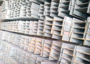

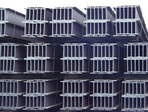
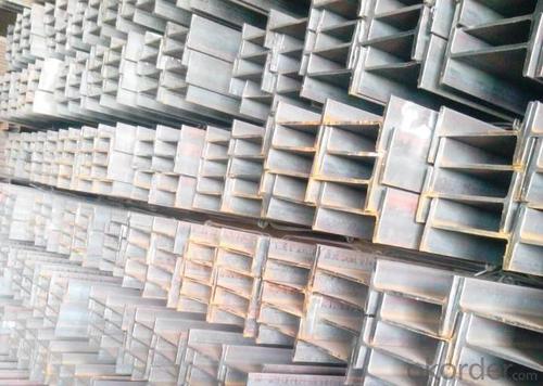


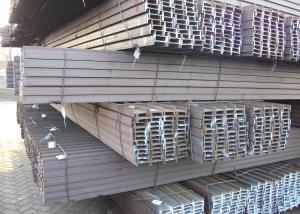
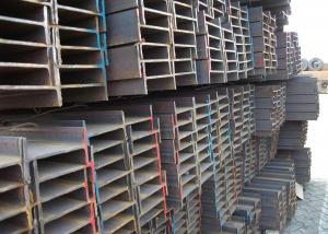
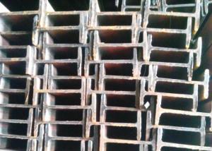
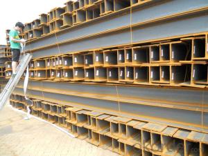
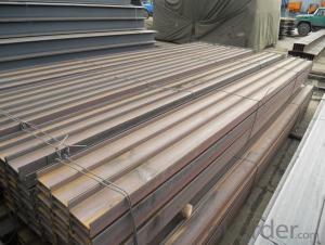
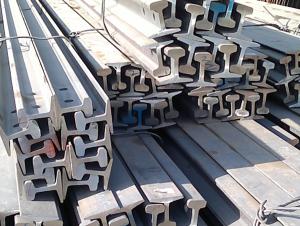
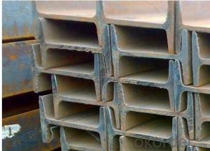
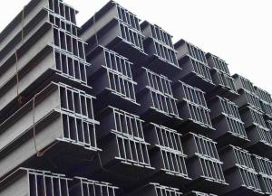
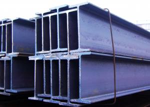
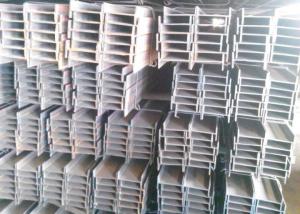
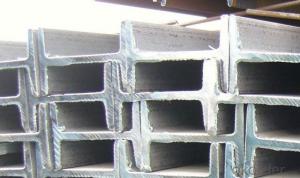
Steel I-Beam
- Ref Price:
-

- Loading Port:
- Tianjin Port, China
- Payment Terms:
- TT or L/C
- Min Order Qty:
- 25MT m.t.
- Supply Capability:
- 500MT Per Day m.t./month
OKorder Service Pledge
OKorder Financial Service
You Might Also Like
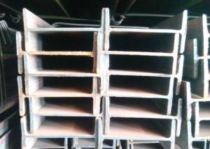
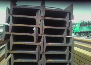
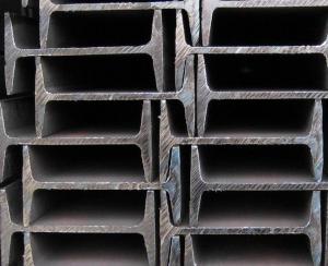
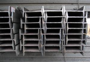
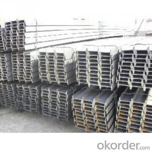
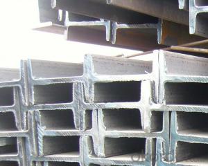
Specifications of Steel I-Beam
Production Standard: GB Standard, EN10025, DIN, JIS, etc.
Material of Steel I-Beam: Q235,SS400,A36,ST37-2,S235JR
Length: 5.8M, 6M, 9M, 12M or as the requriements of the clients
Sizes: 80MM-270MM
Section | Standard Sectional Dimensions(mm) | ||||
| h | b | s | t | Mass Kg/m |
IPE80 | 80 | 46 | 3.80 | 5.20 | 6.00 |
IPE100 | 100 | 55 | 4.10 | 5.70 | 8.10 |
IPE120 | 120 | 64 | 4.80 | 6.30 | 10.40 |
IPE140 | 140 | 73 | 4.70 | 6.90 | 12.90 |
IPE160 | 160 | 82 | 5.00 | 7.40 | 15.80 |
IPE180 | 180 | 91 | 5.30 | 8.00 | 18.80 |
IPE200 | 200 | 100 | 5.60 | 8.50 | 22.40 |
IPE220 | 220 | 110 | 5.90 | 9.20 | 26.20 |
IPE240 | 240 | 120 | 6.20 | 9.80 | 30.70 |
IPE270 | 270 | 135 | 6.60 | 10.20 | 36.10 |
IPEAA80 | 80 | 46 | 3.20 | 4.20 | 4.95 |
IPEAA100 | 100 | 55 | 3.60 | 4.50 | 6.72 |
IPEAA120 | 120 | 64 | 3.80 | 4.80 | 8.36 |
IPEAA140 | 140 | 73 | 3.80 | 5.20 | 10.05 |
IPEAA160 | 160 | 82 | 4.00 | 5.60 | 12.31 |
IPEAA180 | 180 | 91 | 4.30 | 6.50 | 15.40 |
IPEAA200 | 200 | 100 | 4.50 | 6.70 | 17.95 |
Usages of Steel I-Beam
According to the needs of different structures, steel I-beam can compose to different force support component, and also can be the connections between components. They are widely used in various building structures and engineering structures such as roof beams, bridges, transmission towers, hoisting machinery and transport machinery, ships, industrial furnaces, reaction tower, container frame and warehouse etc.
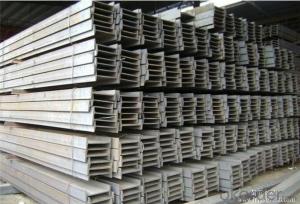
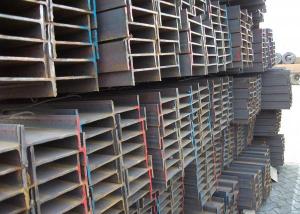
Packaging & Delivery of Steel I-Beam
1. Packing: it is nude packed in bundles by steel wire rod
2. Bundle weight: not more than 3.5MT for bulk vessel; less than 3 MT for container load
3. Marks:
Color marking: There will be color marking on both end of the bundle for the cargo delivered by bulk vessel. That makes it easily to distinguish at the destination port.
Tag mark: there will be tag mark tied up on the bundles. The information usually including supplier logo and name, product name, made in China, shipping marks and other information request by the customer.
If loading by container the marking is not needed, but we will prepare it as customer request.

4. Transportation: the goods are delivered by truck from mill to loading port, the maximum quantity can be loaded is around 40MTs by each truck. If the order quantity cannot reach the full truck loaded, the transportation cost per ton will be little higher than full load.

5. Delivered by container or bulk vessel


6. Delivery time: All the structural steel I beams will be at the port of the shipment within 45 days after receiving the L/C at sight ot the advance pyment.
7. Payment: L/C at sight; 30% advance payment before production, 70% before shipment by T/T, etc.
Production flow of Steel I-Beam
Material prepare (billet) —heat up—rough rolling—precision rolling—cooling—packing—storage and transportation
- Q: What are the different connection methods for Steel I-Beams?
- There are several different connection methods for Steel I-Beams, depending on the specific application and structural requirements. Some of the common connection methods include: 1. Welding: This is the most common method used to connect steel I-beams. It involves melting the base metal and applying a filler material to create a strong joint. Welding provides excellent strength and rigidity, making it suitable for heavy-duty applications. 2. Bolting: Bolts can be used to connect steel I-beams together. This method involves drilling holes in the flanges or web of the I-beams and inserting bolts through these holes, along with washers and nuts, to tighten and secure the connection. Bolting provides ease of installation and disassembly, making it suitable for temporary or adjustable structures. 3. Riveting: Rivets are another traditional method of connecting steel I-beams. This process involves inserting a rivet through pre-drilled holes in the flanges or web of the I-beams and then deforming the rivet to create a permanent connection. Riveting provides high strength and reliability but requires specialized tools and expertise. 4. Adhesive bonding: In some cases, adhesive bonding can be used to connect steel I-beams. This method involves applying a high-strength adhesive to the surfaces of the I-beams and then pressing them together to create a bond. Adhesive bonding can provide a clean and aesthetically pleasing connection, but it may not be suitable for heavy loads or dynamic loads. 5. Mechanical connectors: There are various mechanical connectors available in the market specifically designed for connecting steel I-beams. These connectors are often prefabricated and can be easily installed by bolting or welding. They provide a quick and efficient method of connecting I-beams while maintaining high strength and load-bearing capacity. It is important to consider the specific structural requirements, load conditions, and design constraints when selecting the appropriate connection method for steel I-beams. Consulting with a structural engineer or a qualified professional is recommended to ensure the chosen connection method meets the necessary standards and specifications.
- Q: The difference between I-beam i40a and i40b
- The two weights differ. I40a weighs 67.6kg per metre; i40b weighs 73.9kg per meter.I-beam is also called steel girder (UniversalBeam). It is a strip of steel with an I-shaped section. I-beam is made of ordinary I-beam and light i-beam. It is a section steel whose shape is trough.
- Q: How do steel I-beams compare to timber beams in terms of strength and durability?
- Steel I-beams are generally considered to be stronger and more durable than timber beams. Steel has a much higher strength-to-weight ratio than timber, meaning it can support heavier loads without bending or breaking. Additionally, steel is not susceptible to rot, insects, or fire like timber, which enhances its durability. Overall, steel I-beams are the preferred choice for structural applications where strength and long-term durability are crucial.
- Q: Elevator room in the cement blocks is what to do for?
- The cement block is used to install lift beam, installation height of lift beam elevation, to provide space for the installation of rollers, traction rope accessories, to ensure that the elevator to the top in the bottom and the top box when the elevator is parallel to the ground.
- Q: Can steel I-beams be used for heavy equipment support?
- Yes, steel I-beams can be used for heavy equipment support. Steel I-beams are commonly chosen for their strength and load-bearing capabilities, making them suitable for supporting heavy equipment. They provide structural stability and can effectively handle the weight and stress of heavy machinery.
- Q: What is the supply length of 30# I-beam?
- I-beam, also called steel girder, is a strip of steel with an I-shaped section. I-beam is made of ordinary I-beam and light i-beam. It is a section steel with an I-shaped section. I-beam is mainly divided into ordinary I-beam, light I-beam and H steel three. Due to the relatively high section size and narrow width of ordinary I-beam and light I-beam, the moment of inertia of the two main sleeves of the cross section is different greatly.
- Q: What are the meanings of I-beam BH300 x 200 x 6 x 8 in steel structures?
- I-beam is also called steel girder (English name Universal Beam). It is a strip of steel with an I-shaped section. I-beam is made of ordinary I-beam and light i-beam. It is a section steel whose shape is trough.
- Q: Can steel I-beams be used in retail or commercial buildings?
- Yes, steel I-beams can be used in retail or commercial buildings. Steel I-beams are commonly used in the construction of commercial and retail buildings due to their strength, durability, and ability to support heavy loads. These beams provide structural support for the building's framework, allowing for open floor plans and large open spaces. Additionally, steel I-beams can be easily fabricated and customized to meet the specific needs and design requirements of retail or commercial projects.
- Q: Can steel I-beams be used for rooftop equipment supports?
- Yes, steel I-beams can be used for rooftop equipment supports. Steel I-beams are commonly used in construction for their high strength and load-bearing capabilities. They provide a sturdy and durable option for supporting heavy equipment on rooftops. Additionally, steel I-beams can be easily customized and fabricated to meet specific requirements, making them a versatile choice for rooftop equipment support systems. However, it is important to ensure that the structural integrity of the building can handle the additional weight and that proper engineering calculations are performed to determine the appropriate size and configuration of the steel I-beams to safely support the rooftop equipment.
- Q: What is the lifespan of a painted steel I-beam?
- The lifespan of a painted steel I-beam can vary depending on several factors such as the quality of the paint application, the environment in which it is installed, and the maintenance practices followed. Generally, a well-painted steel I-beam can have a lifespan of 20-30 years or more. However, if the paint is not applied properly or if the beam is exposed to harsh conditions such as extreme temperatures, moisture, or corrosive substances, the lifespan may be significantly reduced. Regular inspections, cleaning, and repainting when necessary can help extend the lifespan of a painted steel I-beam.
1. Manufacturer Overview
| Location | Qinhuangdao, China |
| Year Established | 2000 |
| Annual Output Value | Above US$ 300 Million |
| Main Markets | Mid East; Africa; Southeast Asia; Brazil |
| Company Certifications | ISO 9001:2008; |
2. Manufacturer Certificates
| a) Certification Name | |
| Range | |
| Reference | |
| Validity Period |
3. Manufacturer Capability
| a) Trade Capacity | |
| Nearest Port | Tianjin; |
| Export Percentage | 70% - 80% |
| No.of Employees in Trade Department | 21-50 People |
| Language Spoken: | English; Chinese; |
| b) Factory Information | |
| Factory Size: | Above 400,000 square meters |
| No. of Production Lines | 2 |
| Contract Manufacturing | OEM Service Offered; |
| Product Price Range | Average |
Send your message to us
Steel I-Beam
- Ref Price:
-
- Loading Port:
- Tianjin Port, China
- Payment Terms:
- TT or L/C
- Min Order Qty:
- 25MT m.t.
- Supply Capability:
- 500MT Per Day m.t./month
OKorder Service Pledge
OKorder Financial Service
Similar products

Hot products
Hot Searches
Related keywords

