


Tin-platted Copper-clad Steel Wire
- Ref Price:
-

- Loading Port:
- Guangzhou
- Payment Terms:
- TT OR LC
- Min Order Qty:
- 500 kg
- Supply Capability:
- 400000 kg/month
OKorder Service Pledge
OKorder Financial Service
You Might Also Like


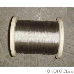
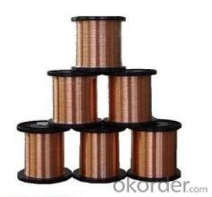
1. Product Description:
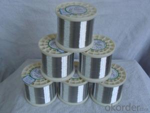
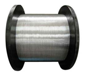
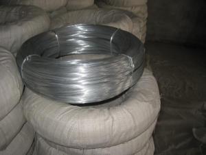
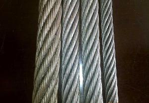
Tinned copper clad steel is made by covering a coating of tin on the surface of copper clad steel wire by hot dip method, the metallic cohesion is perfectly between the layers, and there will be no flaking off during the heat treatment or mechanical workout. The TCCS is the best new clad metal wire instead of tined copper wire. Producible scope: the diameter is from 0.10mm to 1.20mm; the conductivity is from 15% -30%
2. Product Characteristic:
shiny, excellent electrical conductivity, bearing being bended, good tensile strength, excellent welding and corrosion, with light specific gravity, can save resources of copper.
3. Product Specification
Place of Origin: Zhejiang, China (Mainland)
Number: CCS
Surface Treatment:
Coated Type: single wire
Function: shielding
Wire Gauge: 0.10mm-2.00mm
Conductivity: 16%
Copper content: 4%
Surface of ccs: tin plated
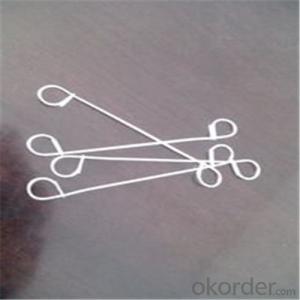
4. Application
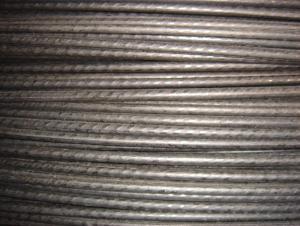
Main Application: flexible coaxial cable, a variety of audio and video cable, vehicle signal cable, network cable, data transmission cables and so on. Tinned copper clad steel can be used in the above cable: cable conductor, braiding and shielding, the single wire conductor and other conductors. Applicable to a variety of electronic components lead wire, such as capacitors, resistors and so on.
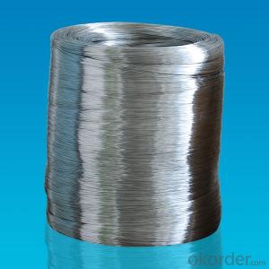
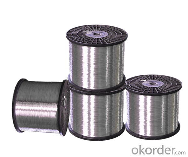
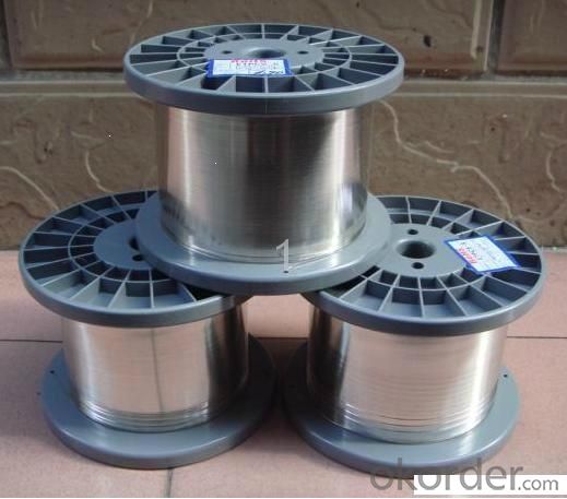
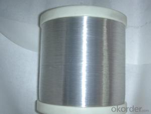
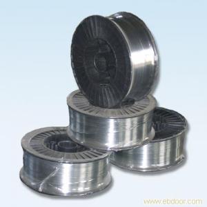
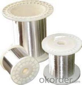
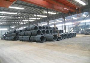
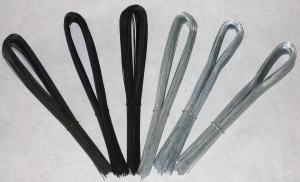
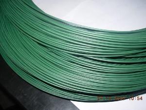
5. Reference Picture


- Q: What would the wire size be for a 3 phase 4 wire - 480/277V - 400A panelboard. Would it be (3) 600mcm w/ (1) 1/0 ground?
- Well not quite: 1. The panelboard is 4 wire therefore the (3) in the description would be (4). The 4th wire is for the neutral and required if you are using the 277. Otherwise the panelboard is a 3 wire board and no 277 2. 600 kcmil copper with 75°C insulation is able to carry 420 A as long as the ambient temperature < 86°F (30°C) and are installed by themselves (not in a raceway/cable tray with other power conductors). If the conductors are aluminum, the temperature is hot, the installation has multiple conductors in the same raceway/cable tray, or the distance is of sufficient length resulting in unacceptable voltage drop, the cable must be derated -- read you must increase the size to 750 kcmil or increase the insulation rating to 90°C The ground conductor should be of sufficient size
- Q: can a positive wire connect a negative and positive terminal together, or can a negative wire connect a positive and negative terminal together? This is regard to speakers in a guitar speaker cabinet. using rca speaker wire which is two wires that can be separated. One is positive and the other negative. If you are only using one half of the wire to wire two speakers in series does it matter if it is the positive(the side with the white stripe) or negative one since wiring in series is positive terminal to negative terminal.
- Wire is wire. There is no positive wire and no negative wire. The wires are colour coded so you can keep track of what connects to what. You can use orange and green wires if you want; just keep track of what you are connecting.
- Q: I bought a wiring harness for my 2001 Ford Focus with a non-blaupunkt factory cassette player. The wiring harness doesn't match up exactly. A reviewer online said his didn't match up either, but still worked. The factory wiring has 7 slots and the one I received has 8. What do you think?Factory wiring on the left, the harness I received on the right:Constant Voltage - Constant VoltageGround - NothingIgnition Voltage - Ignition VoltageConstant Voltage - Illumination/DimmerGround, switched - NothingGround - GroundNot Used - Power AntennaNo Slot Here - Remote Turn onIt's mainly the Constant Voltage - Dimmer connection that worries me.And I know I can just hack up the wiring and skip the harness all together, but I'm trying to keep it simple and neat for the next guy/gal (which may be me for all I know).What do you think?Thanks in advance.
- 2001 Ford Focus Car Stereo Wiring Diagram Car Radio Battery Constant 12v+ Wire: Green/Black Car Radio Accessory Switched 12v+ Wire: Black/Pink Car Radio Ground Wire: Black/Green Car Radio Illumination Wire: Orange/Black Car Stereo Dimmer Wire: N/A Car Stereo Antenna Trigger Wire: N/A Car Stereo Amp Trigger Wire: N/A Car Stereo Amplifier Location: N/A Car Audio Front Speakers Size: N/A Car Audio Front Speakers Location: N/A Left Front Speaker Positive Wire (+): Orange/Green Left Front Speaker Negative Wire (-): Blue/White Right Front Speaker Positive Wire (+): Tan/Green Right Front Speaker Negative Wire (-): Green/Orange Car Audio Rear Speakers Size: N/A Car Audio Rear Speakers Location: N/A Left Rear Speaker Positive Wire (+): Gray/Blue Left Rear Speaker Negative Wire (-): Brown/Yellow Right Rear Speaker Positive Wire (+): Black/Violet Right Rear Speaker Negative Wire (-): Orange/Violet
- Q: why do we use copper wires as connecting wires
- To use something as a connecting wire it should possess some qualities. First it should be a good conductor of electricity, that is it should have free electrons in its configuration. Secondly the substance should be malleable, that is it should be versatile enough to be stretched into wires. And lastly it should be available in abundance and should be economically feasible. As copper satisfies all the above prerequisites it is often used to make conducting wires.
- Q: have black (hot) and 2 whites from the house. Got Black,green.blue.and white from the fan. Any clues on how to wire this? There is a light switch involved. I know to match the colors but what do with the blue (light) wire is beyond me.
- Mark is Correct except for one thing that caught my attention: you said you have 2 White Wires and 1 Black Wire coming from the house.....WHY 2 White Wires and only 1 Black, Doesn't add up Correctly, unless one of those White Wires was marked with a piece of Black Tape to identify it as a second Hot Wire which would then be used to separate the Fan Motor from the Fan Light by each having its own separate power source.......Be Careful!!
- Q: Ok I've been changing the old outlets in the house and all of them were fine until I got to this 1 outlet. The outlet had 1 ground wire, 2 white and 2 black (if that helps). The wires were a little chewed up looking so when I went to wrap the upper white wire to its screw it broke and now the wire won't reach the screw and certain lights in the house won't turn on because of it. I probably should have left it alone because of the condition of the wires but its too late now so how do I go about getting the wire to reach its screw ? Thanks
- using a wire nut just get the same size wire cut it about 4 inches long and make whats called a pig tail use the wire nut to connect the new wire to the short one its most likley a 14/2 wire if its on a 15 amp breaker if its on a 20/amp you should use a 12/2 wire
- Q: The output part of wire plastic and part of wire broken, and the connection lost sometimes, some taps used to wrap up but the connection is still not good.How to fix it permanently?
- Only try to fix it if it is on the lptop side, DON't play with A/C power unless you're qualified. If it is on the safe voltage side you could cut the wire, strip back the wires about 1cm, and twist them together, then solder the wires. Before you join them slide a small piece of heatshrink over one side of it, then after joining and soldering the wires wrap a small amount of electrical tape around the bare wires then slide the heatshrink over it all and heat it up to enclose it all, Fixed ! If you need help with it let me know. Cheers,
- Q: plz answer correctly as soon as possible......why we use stranded 500kV wire?
- There are many uses for stranded wire, from 5V to 500kV, and the reasons are very different. I am assuming since you say 500kV you mean high voltage transmission conductors? If that is the case the reason mainly is because of the physical strength of the conductor and manufacturing processes. For example a solid aluminum conductor with such large diameter is not realistic. When conductor spans large distances the weight of aluminum itself would tear it apart. Therefore a normal conductor would be something like 336 ACSR. ACSR meaning aluminum conductor steel reinforced. Steel is the inner wire for strength, and the outer wire is many aluminum wires wrapped together for carrying the electricity... Hopefully this was of some help.
- Q: A 5.07 m length of 2.1 mm diameter wire carries 703 mA current when 22.3 mV is applied to its ends. Determine the resistivity of the wire.
- Resistance of a wire in Ω R = ρL/A ρ is resistivity of the material in Ω-m L is length in meters A is cross-sectional area in m? A = πr?, r is radius of wire in m Use current and voltage to determine resistance. Plug that into the above and solve for ρ. Be sure to change numbers into meters.
- Q: Hi, I've got two new appliances (range hood fan/light and bathroom exhaust fan). Both are installed but not wired. My house is older, build in 1940s and the previous appliances were wired using the existing copper wiring which runs through the house. I'd like to electrically install these new appliances but am concerned about connecting the new appliance wiring (aluminum wiring i think?) to the copper wiring in the house.Is it safe to pigtail these two wires together? Or is there a better, more safe method?Thanks
- Most building wire is copper, UL wouldn't allow dangerous cords to be used with normal wire.
Send your message to us
Tin-platted Copper-clad Steel Wire
- Ref Price:
-
- Loading Port:
- Guangzhou
- Payment Terms:
- TT OR LC
- Min Order Qty:
- 500 kg
- Supply Capability:
- 400000 kg/month
OKorder Service Pledge
OKorder Financial Service
Similar products

Hot products
Hot Searches
Related keywords

