

Red copper wire
- Ref Price:
-

- Loading Port:
- China Main Port
- Payment Terms:
- TT OR LC
- Min Order Qty:
- -
- Supply Capability:
- -
OKorder Service Pledge
Quality Product, Order Online Tracking, Timely Delivery
OKorder Financial Service
Credit Rating, Credit Services, Credit Purchasing
You Might Also Like


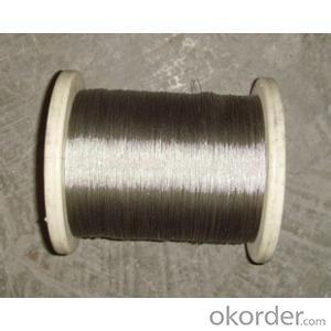
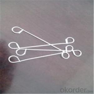
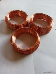
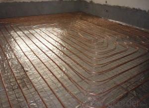
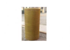
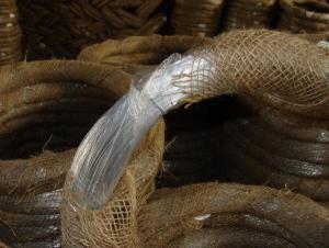
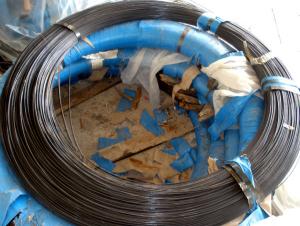
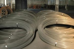
Product introduction: selection of copper wire and then processed, the line is arranged closely
and with a bracket is fixed, or make a small bunch of silk, the product produced is very beautiful,
it is mainly used in the gardens of the binding and Manor decorations. It is the preferred product
for garden binding.The size range of the wire diameter of 0.6mm-6.0mm.
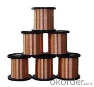
Packing:0.1 to 5kg coil packing,with plastic bracket,label,carton,pallet,or according to customers' requirement.
- Q: The wire is size 10AWG and will be to install a small fluorescent light in a closet. It is coming off of a typical electric outlet. I know someone who is witing it with commercial wire and I think it may be dangerous. Is it?
- that will be safe and it is OK ...not a problem ....
- Q: the fused ignition wire and illumination wire, i cant figure out where they go on a Dual stereo system model1225 Help. ( on a 1990 ranger )
- the ignition wire is going to be a yellow with a black stripe(car wire) and the instruction manual will tell you for the head unit illumination wire i just taped up since my head unit didnt require it =) like they say...if it turns on it dont need it
- Q: There is a circuit with a battery connected to two wires in parallel. Both wires are made of the same material and are of the same length, but the diameter of wire A is twice the diameter of wire B. Answer true or false for the following questionsThe curent through the battery is five times larger than the current through wire B.The power dissipated in wire A is 16 times the power dissipated in wire B.The voltage drop across wire B is larger than the voltage drop across wire A.The resistance of wire B is four times as large as the resistance of wire A.The resistance of wire B is twice as large as the resistance of wire A.
- ***EDIT - CORRECTION*** Thanks Bill (the other Bill) it helps to put numbers on it. ******************** If I understand your question: The curent through the battery is five times larger than the current through wire B. **TRUE** Because: Current A is four times current B. Total current = A+B, or 4+1=5 The power dissipated in wire A is 16 times the power dissipated in wire B. ***FALSE*** (EDIT - I was wrong the first time) Because: Power = VxA The voltage drop across wire B is larger than the voltage drop across wire A. **FALSE** Because: If two wires are parallel voltage is same at ends (Beginning point of A and B is the same poin, ending point of A and B is the same point). The resistance of wire B is four times as large as the resistance of wire A. **TRUE** Because: Resistance inversely proportional to square of wire diameter. The resistance of wire B is twice as large as the resistance of wire A. **FALSE** Because: Resistance inversely proportional to square of wire diameter. Also check out web site shown below. Let me know if this helps Bill
- Q: why do screen filters have wires with them?
- For Earthing to stop static Electricty, connect the wire to the Casing
- Q: I am replacing old 3 button (vertically aligned) light switch. There is 1 thick wire wrapped in white, 1 thick wire wrapped in black and 4 thin wires wrapped in black. I attached the white wire to the common wire screw and put the remaining wires around the screws. I am also replacing a toggle switch that will control the vanity lights above the sink. There are 4 clumps of wire coming through the box. The copper grounds are all twisted together, and there are multiple strands of white covered wire twisted together and then the 5 black cover wires and 1 white covered wires. After hooking it all up, it doesn't do anything. No lights, fan or heat lamp. What did I do wrong?
- Jeff Verde nailed it but forgot one thing. Never assume that the last person that installed wiring hooked it up to the right colors! I've even seen people use a hot wire (Black) as the ground. Never assume it's right to start with!
- Q: can anyone please tell me what does hook-up wire mean and how does it differ from other kinds of wires such as light duty and heavy duty?Also,which one should I use for breadboards?
- Hookup wire is a term usually reserved for wire sizes smaller than 16 AWG, usually single strand conductor. It is generally used in applications where current-carrying capacity is not of prime importance. Breadboarding is one of these applications, but usually uses 22AWG or smaller wire.
- Q: im hooking a amp up and i need to run my remote wire to my ignition wire
- I have wired up alot of amps and the remote wire on the amp should be connected to the power antenna/amp turn on wire on the stereo head unit. This allows the amp to only turn on when the stereo is on. If you are connecting an amp to a factory stereo,I see why you would need to find an ignition wire. You need to probe the fuse panel with a 12 volt test light to find a circuit that only comes on with the key. Usually there is a spare accessory fuse location just for this. Buy a fuse tap or specialty fuse from a auto parts store to connect your remote wire to. There is very little current draw to turn on the amp,so almost any circuit on the fuse panel will work if it is only on with the key.
- Q: Ok You know the speaker wires that go to the back of the subwoofer? The metal part that comes out of the wire came out of the wire, and it makes a funny sound or no sound at all. How can I fix this? Also, I cut the wire and put the copper wires into the subwoofer, it works so so, any sugestions? lew
- Connection to a subwoofer is either bare wires or rca type jack (male end) and are eith plug to the rca jack (female) or a screw post for the wires. From the sound of it you are using the rca type, it is is just buy a new one the are inexpensive to replace. You need to have a good solid connection for you sub. Hope this helps.
- Q: Okay, magnet wire is coated with some red fancy insulation. Is that just an enamel?If so, enamel coated copper wire magnet wire would be the same thing.I want to build a loudspeaker. This what I need?Are the coils used in loudspeakers the same ones used in inductor coils?One interesting question,When Faraday was experimenting with the effects of magnetism on electricity, how in the hell did he figure out the magnetic field increased with the number of turns of copper in his coils!I'm only assuming Faraday didn't have insulated copper wires.Lmao, if they aren't insulated, how in the heck is he suppose to know how much the field is increased. The Coil would just become a big conductor lol
- Today we always use magnet wire from inductors, transformers and speaker, but Faraday didn't have any so he just used insulated wire. He was smarter the you and me, so if we know you need insulated wire, so did he.
- Q: I have a physics project and my teacher is saying that we should do a wire loop toy?? What the hell is that. Can anybody give me a example and how it is related to physics?? Pls answer back
- Wire loop toys mean wire connected to your toy and a handle along with battery.
Send your message to us
Red copper wire
- Ref Price:
-
- Loading Port:
- China Main Port
- Payment Terms:
- TT OR LC
- Min Order Qty:
- -
- Supply Capability:
- -
OKorder Service Pledge
Quality Product, Order Online Tracking, Timely Delivery
OKorder Financial Service
Credit Rating, Credit Services, Credit Purchasing
Similar products
Hot products

Hot Searches
Related keywords

