
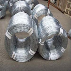
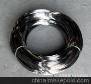
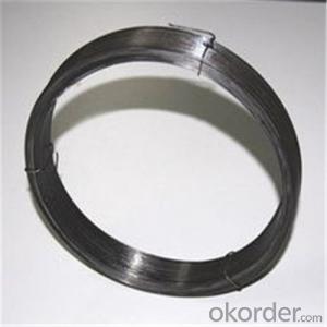
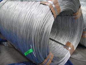
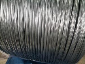
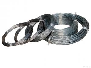
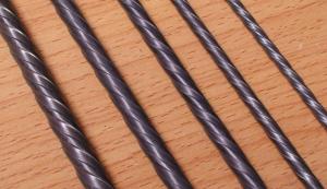
Hot Dipped Galvanized Steel Wire 3.0mm For Chain Link and Gabions
- Ref Price:
-

- Loading Port:
- Tianjin
- Payment Terms:
- TT OR LC
- Min Order Qty:
- 10 m.t.
- Supply Capability:
- 1500 m.t./month
OKorder Service Pledge
OKorder Financial Service
You Might Also Like


Commercial Galvanised Steel Wire
(1) Quality : Meet GB/T 343 standard and other requirements of relevant standards .
(2) Zinc Coating: Meet GB/T 15393 standard and other requirements of relevant standards .
(3) Raw Material : Wire rod ——1006 , 1008 , 1018 , Q195 , etc, and zinc with 99.995% purity.
(4) Tensile Strength Range
Size (mm) | Tensile Strength (mpa) |
0.15-1.60 | 290-550 |
0.65-1.60 | 400-550 |
1.61-6.00 | 400-1200 |
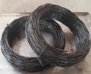
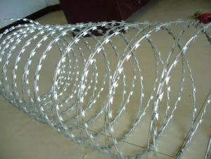
(5) Application : Used in wire mesh , artware , metal hose , binding for agriculture and construction , etc.
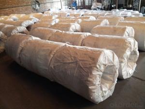
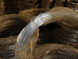
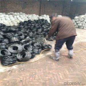
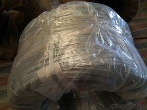
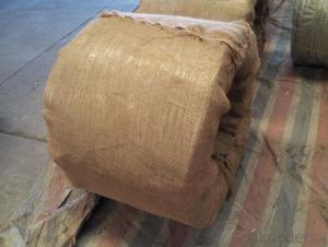
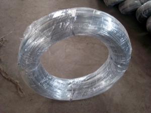
(6) Packing
Size (mm) | Coil Size | Spool Packing | Big Coil Packing | |
ID (mm) | OD (mm) | |||
0.15-0.26 | 6 inch | 1-14kg/spool | ||
0.27-0.60 | 8 inch | 1-100kg/spool | ||
0.61-1.60 | 12/14/16 inch | 1-100kg/spool | 250-400 | 400-770 |
1.61-6.00 | 14-500kg/spool | 450 | 800 | |
508 | 840 | |||
(7) Zinc Coating
Meet GB/T 15393 standard.
Size (mm) | Weight of Zinc-Coating ( g/m2 ) | |||||||
A | AB | B | C | D | E | F | ||
A1 | B2 | |||||||
≤0.25 | 30 | 20 | 18 | |||||
>0.25-0.40 | 30 | 25 | 20 | |||||
>0.40-0.50 | 30 | 20 | ||||||
>0.50-0.60 | 35 | 20 | ||||||
>0.60-0.80 | 120 | 110 | 40 | 20 | ||||
>0.80-1.00 | 150 | 130 | 45 | 25 | ||||
>1.00-1.20 | 180 | 150 | 50 | 25 | ||||
>1.20-1.40 | 200 | 160 | 50 | 25 | ||||
>1.40-1.60 | 220 | 180 | 50 | 35 | 30 | |||
>1.60-1.80 | 220 | 180 | 70 | 40 | 30 | |||
>1.80-2.20 | 230 | 200 | 80 | 50 | 40 | |||
>2.20-2.50 | 240 | 210 | 80 | 55 | 40 | |||
>2.50-3.00 | 250 | 230 | 90 | 70 | 45 | |||
>3.00-4.00 | 270 | 250 | 100 | 85 | 60 | 30 | ||
>4.00-5.20 | 290 | 270 | 110 | 95 | 70 | 40 | ||
>5.20-6.00 | 290 | 270 | 245 | 110 | 100 | 80 | 50 | |
- Q: I bought a single pole dimmer switch to install in my dining room and when I took the old switch out nothing looked right. There are two wires which were joined together by another single wire which was attached to the top screw. There was another single wire (I believe the ground wire) attached to the bottom screw. I disconnected the first two wires and attached them separately to the black wires on the dimmer and attached the ground wires together. It didn't work. I've tired several different times with no luck. I put the wires back the way they were and attached them to the old switch and they no longer work ether. Help! How can I fix this problem? The old wires appear to be a very thick copper covered in black plastic and cloth.....
- How To Install A Dimmer
- Q: do speakers function better with thick or thin wires??
- The wiring in your car audio system is very important. The higher the gauge of wire you choose to use the less resistance will be placed on the amplifier or head unit (which have internal amplifiers). This means more power to the speakers and ultimately more quality sound. It depends on the wattage of the system to determine the appropriate gauge of wire but as a rule the bigger the better. I would recommend getting a good quality speaker wire. Good speaker wires use the most conductive metals for the wire material, such as copper. They feature thick jackets that wont wear through from rubbing and vibrations. Choose a good 16-18 gauge wire from a company like Streetwires. Dont cheap out on your speaker wire its an important part of your installation.
- Q: Is it okay to solder wrapping wire to a mother board, I am just asking because the wires are called WRAPPING.
- except you're honestly helpful that the solder is lead unfastened, do no longer use it. Plumbing solder is ordinarily lead unfastened yet electric and sturdy sheet metallic solder pick no longer be. and that i'm uncertain how mind-blowing tin, the different important element of solder, is in terms of leaving black marks on the floor even however somewhat risk-free.
- Q: I have a 1997 Dodge Neon 2DR and i did a electric door and mirror conversion but i cannt figure out the wiring... how would i go about figuring it out... can some explain or better show me how a basic lock and mirror controls are wired
- i own a repair shop,and if you,ll get a good Haynes repair manual on it,this will have the wiring diagrams in it,for doing this ,that's about the only way you can wire it up right on this job,good luck,i hope this help,s.
- Q: I recently took out my old ceiling fan, and now there is a Black, Red, And White Wire hanging from the ceiling, I bought a track light that has a box with a Green, White, and Black wire in it. Which wires am i supposed to connect,It's for the light Switch, and I'm not sure when the house was built, its a Reading, PA Row house.
- This is really simple... The RED is the HOT WIRE for one of the two switches The BLACK wire is a hot Wire for the other of the two switches. The WHITE is the RETURN for both and of course the BARE COPPER WIRE is the ground. So... terminate the red.. Connect black to black, white to white and copper to copper. The switch that controlled the BLACK circuit will now run the track lights.
- Q: Im installing a motion sensor which comes with 3 wires,red black and white and want to connect it to a indoor light that only comes with 2 wires white and black.How do I go about installing them and powering them?
- Hook the white wire to the white on the fixture and the white coming in. The black coming in gets wired to the black wire on the detector. The red gets hooked the the black in the fixture.
- Q: where also is fourth wire hooked in?
- If it is coming from the box at the street into your circuit breaker panel, I'll take a guess. Earth ground (Usually connected to a copper water pipe or a metal pole driven deep into the ground) Neutral (0V) +120 V (Most household circuits) +220 V (Dryers, stoves, possibly air conditioners and other devices needing lots of power. These have special plugs.) Unless you are ABSOLUTELY sure you know what you are doing (and it sounds from your question like you may not be) DO NOT mess around with mains wiring in your house and especially wiring coming into your house, since that isn't even on a surge protector to keep you even remotely safe. If you mess around with this stuff without knowing what you are doing, you could wind up DEAD or in the hospital VERY easily. I can't stress enough how dangerous electricity in large quantities is.
- Q: Need ro know where to put the wires correctly
- there are 2 110 volt wires black 1 neutral white and 1 ground green, how to hook them up if you don't know call an electrician before you burn the house down or kill someone.
- Q: wiring diagram
- I don't believe that such a thing exists. What is your question specifically? Are you installing a remote receiver inline? If so, the wires should be individually labed. Connect the white wire coming from the ceiling to the white wire labeled 'line' or 'to supply'; connect the black wire coming from the ceiling to the black wire labeled 'line' or 'to supply'; connect the green wire from the fan, green wire from the mouth, and the green or bare copper wire coming from the ceiling (if there is one) together; connect the white wire coming from the fan to the white wire labeled 'load' or 'to fan'; connect the black wire coming from the fan to the black wire labeled 'load' or 'to fan'; if you're installing a light kit on this fan, connect the extra wire, which is probably either black with white stripes or red, to the wire labeled 'to light'
- Q: im hooking up a air/fuel tomorrow and i need to know what color the wire for the sensor signal is on my rt... i have 4 wires and heres the colors and were they are from. t/w or o/t from c124 b/lbl from c14 and c315 b gound and o/dg from fuse a... need answer thanks
- It should be the BLK/ LB wire (although my wiring schematic shows that wire BLK/ GREEN), It will be the only circuit that have a varying voltage between 0-1 volt. Probe the wires with a DVOM and determine which wire has the signal, one wire will supply B+ for the heater, one is heater ground, one is reference supply voltage and one is signal return The signal return is the circuit you need to tap.
Send your message to us
Hot Dipped Galvanized Steel Wire 3.0mm For Chain Link and Gabions
- Ref Price:
-
- Loading Port:
- Tianjin
- Payment Terms:
- TT OR LC
- Min Order Qty:
- 10 m.t.
- Supply Capability:
- 1500 m.t./month
OKorder Service Pledge
OKorder Financial Service
Similar products
Hot products


Hot Searches

