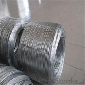

Commercially Galvanized Steel Wire
- Ref Price:
-

- Loading Port:
- China Main Port
- Payment Terms:
- TT OR LC
- Min Order Qty:
- -
- Supply Capability:
- -
OKorder Service Pledge
OKorder Financial Service
You Might Also Like


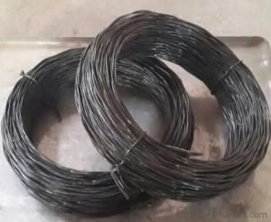
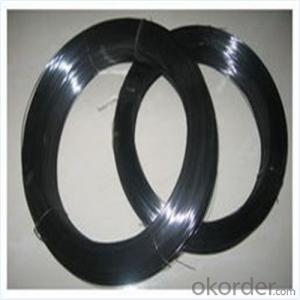


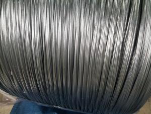
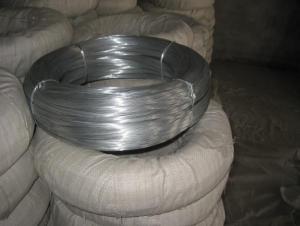
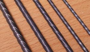
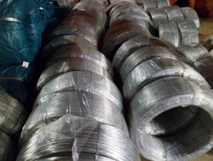
Commercial Galvanised Steel Wire
(1) Quality : Meet GB/T 343 standard and other requirements of relevant standards .
(2) Zinc Coating: Meet GB/T 15393 standard and other requirements of relevant standards .
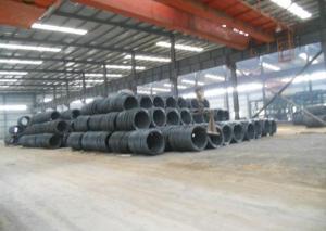
(3) Raw Material : Wire rod ——1006 , 1008 , 1018 , Q195 , etc, and zinc with 99.995% purity.
(4) Tensile Strength Range
Size (mm) | Tensile Strength (mpa) |
0.15-1.60 | 290-550 |
0.65-1.60 | 400-550 |
1.61-6.00 | 400-1200 |
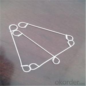
(5) Application : Used in wire mesh , artware , metal hose , binding for agriculture and construction , etc.
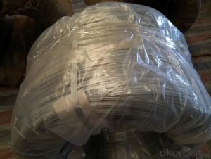
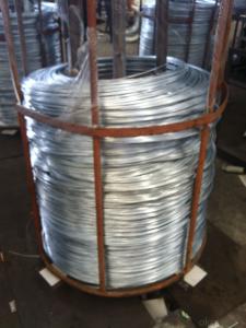
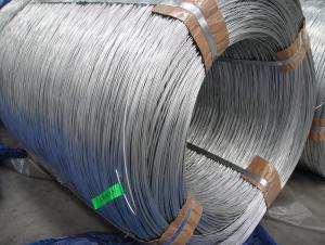
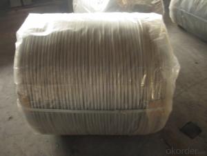
(6) Packing
Size (mm) | Coil Size | Spool Packing | Big Coil Packing | |
ID (mm) | OD (mm) | |||
0.15-0.26 | 6 inch | 1-14kg/spool |
|
|
0.27-0.60 | 8 inch | 1-100kg/spool |
|
|
0.61-1.60 | 12/14/16 inch | 1-100kg/spool | 250-400 | 400-770 |
1.61-6.00 |
| 14-500kg/spool | 450 | 800 |
508 | 840 | |||
(7) Zinc Coating
Meet GB/T 15393 standard.
Size (mm) | Weight of Zinc-Coating ( g/m2 ) | |||||||
A | AB | B | C | D | E | F | ||
A1 | B2 |
|
|
|
|
|
| |
≤0.25 |
|
| 30 | 20 | 18 |
|
|
|
>0.25-0.40 |
|
|
| 30 | 25 | 20 |
|
|
>0.40-0.50 |
|
|
|
| 30 | 20 |
|
|
>0.50-0.60 |
|
|
|
| 35 | 20 |
|
|
>0.60-0.80 | 120 | 110 |
|
| 40 | 20 |
|
|
>0.80-1.00 | 150 | 130 |
|
| 45 | 25 |
|
|
>1.00-1.20 | 180 | 150 |
|
| 50 | 25 |
|
|
>1.20-1.40 | 200 | 160 |
|
| 50 | 25 |
|
|
>1.40-1.60 | 220 | 180 |
|
| 50 | 35 | 30 |
|
>1.60-1.80 | 220 | 180 |
|
| 70 | 40 | 30 |
|
>1.80-2.20 | 230 | 200 |
|
| 80 | 50 | 40 |
|
>2.20-2.50 | 240 | 210 |
|
| 80 | 55 | 40 |
|
>2.50-3.00 | 250 | 230 |
|
| 90 | 70 | 45 |
|
>3.00-4.00 | 270 | 250 |
|
| 100 | 85 | 60 | 30 |
>4.00-5.20 | 290 | 270 |
|
| 110 | 95 | 70 | 40 |
>5.20-6.00 | 290 | 270 | 245 |
| 110 | 100 | 80 | 50 |
- Q: What would the wire size be for a 3 phase 4 wire - 480/277V - 400A panelboard. Would it be (3) 600mcm w/ (1) 1/0 ground?
- Three phase 3 wire is often called a 'delta' connection since the load(s) are distributed between each pair of phases. The 4 wire systems are also called 'Y' systems since the loads are distributed between each phase and a 4'th 'common' phase. The 4 wire system is intrinsically a bit safer since the common phase can also be made electrically neutral (ground). Doug
- Q: just bought a brinks indoor motion sensor switch and having problems installing. the regular light switch has 2 black wires that was connected to one end and a red to the other. the white wires in the wall are already together. the motion sensor switch has black, blue, red wires and its ground wire. the instructions says not to use the red wire for single switch so confused on how to wire them.
- I would ignore the current setup and do what Brinks says. You can try using the wiring and capping the wires not used, test and if it works, perfect!
- Q: I want to get an underground fence but i cant figure out what the difference in the wire they use and regular insullated wire. What is the difference and why can't i use regular wire instead of the wire that comes with the kit
- There isn't anything special about the wire that comes with the kit, it is just wire. If you have already installed the fence and just need to enlarge the area you can use your own wire just make sure it is the same gauge wire as is already hooked up.
- Q: 1. what is drive-by-wire?2. what is drive-by-brake?
- think maybe think of road as wire learn how and when to brake but this might be what it is
- Q: I know what spark plugs are and where they are... but not sure what is meant by wires...For example checking/replacing spark plugs and wires to see if a problem is fixed..Are wires what hookup to the spark plugs from the (distributor?)
- The proper name for spark plug wires is: Ignition Wires. You're right, they are the leads that run from the distributor or ignition coil pack to the spark plugs. Some newer cars don't have ignition wires as such. A timed low voltage signal runs from small electrical wires directly to individual ignition coils which snap directly onto the spark plugs. Newer Toyota's are arranged like this.
- Q: Just got a 540 wat sound system but the speaker wires are only 5 feet, so I want to add about another 10 or 15 feet.
- It is an easy fix. Get the same kind of wire that you now have. I live in Sacramento...I believe Home Depot or other similar stores may carry that wire. Cut the existing wire, peel back the covering, and expose each wire...at both ends of the cut. Do the same for the new wire extension. Strip each of all wires about one half inch. Connect each wire...you can solder, use a crimp, heat shrink, or just simply tape. It's not a big deal. When all the wires are connected, tape them all together so it looks neat!!!.
- Q: If you put clay over wire and bake it would the wire melt and ruin the sculpture?Details on wire:I'm not sure what kind of wire it is but it says Bright Floral Wire..Wire is silverDetails on Clay:Again, im not sure what clay...its from polyform products and it says Premo Sculpey so im guessing Polymer? :#92;Clay is Black.Bakes for 275F (130C)30 minutes per/par/por1/4 in (6mm)
- (Premo okorder /
- Q: Given following setup of three wires in the plane of the page with I1 = 1.3 A (to the right), I2 = 3.4 A (to the right), I3 = 4.5 A(to the left) and each wire is separated by 3 m.I'm completely lost, I need to..1. What is the direction of the magnetic field at wire 3 due to wires 1 and 2?2. What is the direction of the force on wire 3 due to wires 1 and 2?Any help would really be appreciated! Thanks!
- I assume that those wires are sitting parallel 3 m apart from one another. 1. The magnetic field around a wire forms concentric circles around the wire. Wire 1 and Wire 3 are parallel so when you draw a concentric field line around Wire 1 with radius 6 m, you get a magnetic field line passing Wire 3 at a right angle. And a concentric field line around Wire 2 with radius 3 m passes Wire 3 at a right angle. Both magnetic fields have the same direction because the current in both wires flows in the same direction (to the right). Using the right-hand rule, you can find that the magnetic field at wire 3 due to Wire 1 and Wire 2 goes into the page. Ans: Into the page 2. The force on a wire can be calculated in the following manner: I X B * L. Here I is the current on Wire 3, B is the magnetic field due to Wire 1 and Wire 2, L is the length of Wire 3, and X is the cross product operator. So I cross B would give the direction of the force. Now use the right-hand rule, I cross B will give the force direction pointing down. This means the force due to the magnetic field would repel Wire 3 from Wire 1 and Wire 2. Ans: The force on Wire 3 due to Wire 1 and Wire 2 would repel Wire 3 from them.
- Q: Ok. so i wired my cd deck into my 92 buick, but everytime i start the car i have to manually turn on the cd deck. i also have to change the settings everytime! and once i turn off the car the setting will not save and the setting will be lost. Now everytime i turn my car on i have to manually put the settings again! this did not happen in my old car! and i think it might be the wiring! Because the last cd deck i had did save the settings! and would turn thge cd player on everytime i turned on my car!! and it would play the track back, right where i left off. please help! i did attach the yellow cable wire the red cable to the battery current.? is there a problem!
- You should have the yellow power wire connected to constant power and the red wired to ACC. You don't and this is why it's bahiving the way it is.
- Q: Ok, bought this mower at an estate auction for next to nothing. It looks like its never been used. Previous owner ripped out all the wires to the ignition switch so it wouldn't sell I guess. It's the craftsman lt 1500. Model number 247.288812. It has the 17.5hp bs motor in it. Does anyone know the correct way the wires go to the switch? There are 3 red wires so its a bit unlike what im used to. Thanks in advance!
- On my sears mower with an electric clutch the switch is wired like this. G terminal is a black wire to ground. B terminal is a red wire to the ammeter. S terminal is a white wire to a safety switch. M terminal has two black wires one to the ignition coil and the other to a safety switch. L teminal is a red wire to the alternator and a red wire to the PTO switch.
Send your message to us
Commercially Galvanized Steel Wire
- Ref Price:
-
- Loading Port:
- China Main Port
- Payment Terms:
- TT OR LC
- Min Order Qty:
- -
- Supply Capability:
- -
OKorder Service Pledge
OKorder Financial Service
Similar products

Hot products


Hot Searches
Related keywords

