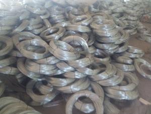

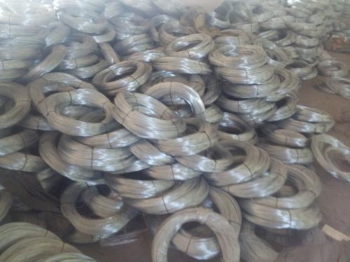

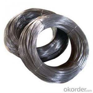
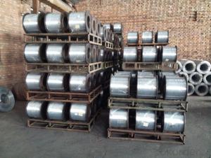
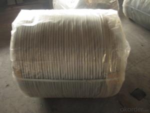
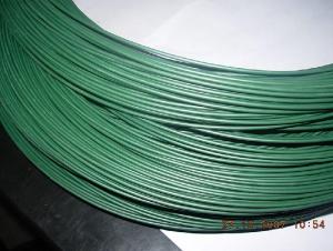
Galvanized Binding Wire
- Ref Price:
-

- Loading Port:
- China Main Port
- Payment Terms:
- TT OR LC
- Min Order Qty:
- -
- Supply Capability:
- -
OKorder Service Pledge
OKorder Financial Service
You Might Also Like


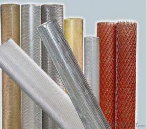
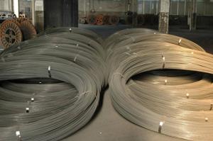
Electro Galvanized Wire:
Electro galvanized wire ranging from BWG8# to BWG16# is the mostly used for customers. We also offer thinner galvanized wire down to BWG5# or up to BWG28# upon customers specific order. Single coil package for electro galvanized wire can be as small as 10 kg and up to maximum 1000 kg per coil.
Electro Galvanized Wire Processing & Features:
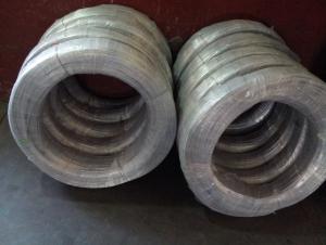
This kind of galvanized wire is made with choice mild steel, through wire drawing, wire galvanizing and other processes. Electro galvanized wire has the characteristics of thick zinc coating, good corrosion resistance, firm zinc coating, etc.
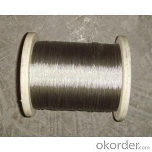
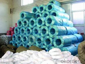
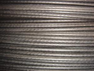
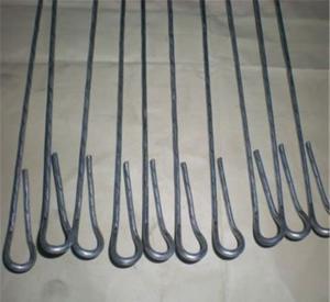
Forms of Supply:
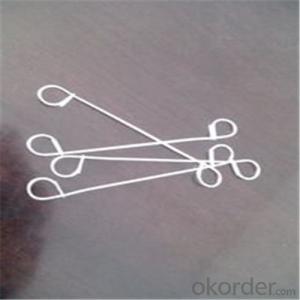
Electro galvanized wire can be supplied in the form of coil wire, spool wire or further processed into straightened cut wire or U type wire.
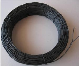
Electro galvanized wire applications:
Electro galvanized wire is mainly used in construction, express way fencing, binding of flowers and wire mesh weaving.
Electro galvanized iron wire, electro galvanized steel wire, electro galvanized wire.
BWG6-22 5.0MM-0.8MM.
Zinc coat: 5-25g/m2.
Tensile strength: 35-120kg/mm2.
ZINC COATING TABLE
SIZE mm | (g/㎡)Min. zinc coating | |||||||
A | AB | B | C | D | E | F | ||
A1 | B2 | |||||||
≤0.25 | 18 | 15 | 12 | 5 | ||||
〉0.25-0.40 | 25 | 20 | 12 | 5 | ||||
〉0.40-0.50 | 25 | 20 | 15 | 8 | ||||
〉0.50-0.60 | 25 | 20 | 15 | 8 | ||||
〉0.60-0.80 | 20 | 15 | 10 | |||||
〉0.80-1.20 | 25 | 18 | 10 | |||||
〉1.20-1.60 | 25 | 18 | 12 | |||||
〉1.60-1.80 | 100 | 70 | 40 | 30 | 20 | |||
〉1.80-2.20 | 105 | 80 | 50 | 40 | 20 | |||
〉2.20-2.50 | 110 | 80 | 55 | 40 | 25 | |||
〉2.50-3.00 | 120 | 90 | 70 | 45 | 25 | |||
〉3.00-4.00 | 100 | 85 | 60 | 30 | ||||
〉4.00-5.00 | 110 | 95 | 70 | 40 | ||||
- Q: The outlet box has 2 black wires capped together, 2 white wires capped together, 2 bare wires capped together, and a single red wire. The light fixture I want to install is a two bulb fixture that has 2 black wires, 2 white wires, and 1 bare wire.
- It is obvious from the question that you have zero knowledge of wiring. While this is an extremely basic thing to do, I think it is better to get a professional so you and your house will be safe. Electricity is too dangerous to do without even the most basic understanding of safe procedures and standards. You will get people telling you how easy this is, but I would rather have you safe than try this your self.
- Q: I am doing wiring in my shed on preexisting light fixtures and outlets. the wiring that was disconnect from that carried the electricity to it. What I am trying to do is have all the light fixtures work of an extension cord. I have another extension wire connected to that with the +, - and 0 showing. The fixtures have 3 wires coming out of them what I think to be the power in, power out, and switch. On the fixture on the end I connected my extension cord thing and it work, BUT only that one. The rest of the fixtures did not work, I do see anything wrong. What I thought was that I was connecting to the switch wire so I changed it and it just buzzed with blue light. What is going on?
- the rest of your light fixtures maybe wired through a switch. you would have to hook your extension cord to the switch but you also need to connect the common neutrals and grounds to the cord as well.
- Q: how do i tap a speaker wire? car audio not really my department
- Just buy a wire stripper, strip the wire and connect the new wire. Remember to wrap electrical tape around it and you're done. You can also buy wire taps but they sometimes don't work due to a bad connection. Stripping the wire is the best solution.
- Q: Stereo wire digram
- you mean cutlass? i would recomend getting a wire harness from a audio store but here is the diagram Car Radio Constant 12V+ Wire: Orange (memory) Car Radio Ignition Switched 12V+ Wire: Yellow Car Radio Ground Wire: Black Car Stereo Illumination Wire: Gray Car Stereo Dimmer Wire: Brown Car Stereo Antenna Trigger Wire: Pink Car Stereo Amplifier Trigger Wire: N/A Front Speakers Size: 3 1/2″ Front Speakers Location: Dash Left Front Speaker Wire (+): Tan Left Front Speaker Wire (-): Gray Right Front Speaker Wire (+): Light Green Right Front Speaker Wire (-): Dark Green Rear Speakers Size: 4″ Speakers x 10″ Rear Speakers Location: Rear Deck Left Rear Speaker Wire (+): Brown Left Rear Speaker Wire (-): Yellow Right Rear Speaker Wire (+): Dark Blue Right Rear Speaker Wire (-): Light Blue
- Q: wire is 4.5 ft from the pole. (a) How much wire is used? (b) How high up the pole is the wire connected?
- Wire length = 4.5' / cos 80 degrees = 25.91 feet Distance up the pole to where the wire is connected = 4.5' (tan 80 degrees) = 25.52 feet
- Q: running wire to a pool motor, it is 1.5 hp, they pulled 10 guage wire and the breaker keeps tripping , do I need heavier wire?
- Depending on the distance, heavier wire might help. It's possible that there is too much voltage drop in the wire during motor starting. That would lead to heavy startup currents being drawn for longer periods. The pump manufacturer should have wire size / distance recommendations. Voltage and current measurements at the pump during startup with min/max peak holding meters should reveal the problem. Don
- Q: For my braces, the top wire where my two front teeth are, I can push the wire and it sort of bend. I don't know if this is normal or not. Can someone tell me?
- Just ask your dentist. have your mom call and ask.
- Q: I'm just wondering would i be able to connect a split 8 gauge wire with wire nuts like i'll explain:Use two wire nuts instead of one and divide the copper wire on both ends and wire nut both sides together with 2 nuts. The whole apparatus would look kinda like this:----lt;gt;---- with the wire nuts connecting the two arrow thingsThanks anyone
- Even though you had been wise to make use of the noalox, or antioxidant, i might ratehr endorse that you get the suitable gauge of wire in copper and rewire the entire circuit. The intent that I say that's that your oven is a excessive resistance circuit and aluminum does no longer like high resistance. With excessive resistance on aluminum, the aluminum wire will start running or moving under the strain and can eventually burn out the connection. In the event you have got to leave it aluminum, don't use a wire nut, but get a split nut from an electrical provide, use teh same goop on it, then get two wrenches for the best way that you just ought to screw the break up bolt to the nut, tighten the item down as tight as humanly viable, the wrap it with a specified tape that the electrical give may also have. It's not the commonplace electrical tape, but a stretchable tape and also you wrap it tight at the least 3 or a bit of extra inches on all sides of the nut. This may insulate the connection in order that it are not able to be shorted out in any respect. Mine had the same aluminum connection and when I changed the stove, which was difficult wired to the stove, I simply replaced the entire wire. Mainly the field is just not too some distance away fromthe stove due to the fact it wants to be as just about it to decrease resistance. To scan what you have got performed, that you would be able to take a low-cost volt meter from Radio shack, set it on the correct settings for measuring voltage on 220, and if the needle goes to 220 + or - a bit, you're nice in the meanwhile.
- Q: I currently have a ceiling fan wired to a dimmer wall switch that controls the fan and the light, not good I know. I would like to set up the dimmer switch where it controls the light only and then i can use the fan pull switch for the fan. but i am not sure how to wire this with my current wires. In the wall box where the dimmer switch is I have two sets of wires coming from two different locations. one set has a black, red, white, and green. the other location has black, white and copper. currently the green and copper are connected and capped, the two whites are connected together and capped, two blacks are and connected to the black wire coming from the dimmer and the red is connected to the other black wire from the dimmer. how would I wire the dimmer switch to only control the light and not the fan? I want to make sure i do this safely.any assistance is greatly appreciated.
- Ok, leave the copper and green wires alone as well as the white wires. Now the red and black coming from the same set should be your fan/light switch legs with red being light and black for fan itself. You may have to go into the fan ceiling box itself as it sounds the fan and light kit are connected to red wire in ceiling box especiallly if dimmer switch is controlling both. The other blacks are power legs. If both wires from fan/light are tied in with red wire, seperate them and connect the blue wire from light kit to red and cap off. With switch off, connect black wire from fan to those black wires that are capped off in box. If this isnt right connections, contact me via my email address on profile
- Q: I attempted to change a bathroom fan to a new one with the help of a friend. He disconnected all the wiring without paying attention to what he was doing and what was wired where. We have a set of wires coming from somewhere (I presume the fuse box) to the fan that is hot regardless of the switch being on or off. That has a black, white and naked wire in it. Then we have another wire that comes from the switch that has black, white and naked as well. The fan has black, white and green. Can someone please tell me how to connect these as we have tried everything and the only thing that works is wired to the constant hot which of course won't allow us to turn the fan off with the switch...
- 1) Turn off the power. 2) Install the fan completely into desired location. 3) Insert both wires into fan's junction box. 4) Twist the two bare wires together, install crimp sleeve onto them at the twist. 5) Find the green screw and connect ONE of these bare wires under it and tighten it down. 6) Cut the OTHER excess wire and fold all this connection up into the junction box. 7) Take the white wire that is coming from the (I presume the fuse box) , and connect it to the white wire that goes to the fan itself. Strip 1/2 of insulation and twist the wires together, install a wire-nut and fold this into the fan's junction box. 8) Take the black wire that comes from the switch and connect it to the black wire that goes to the fan itself. Strip 1/2 of insulation, twist the wires together, install a wire-nut and fold this into the fan's junction box. 9) All that's left is the black wire that is coming from the (I presume the fuse box) , and the white wire that comes from the switch. Strip 1/2 of insulation, twist the wires together, install a wire-nut. 10) Take a black Sharpie pen and color this connection's white wire black and fold this into the fan's junction box. This is known as a switch-leg. 11) Restore power and test. I will you with these two thoughts: 1) It is always best to hire a pro for this type of work. 2) Good luck and may God bless.
Send your message to us
Galvanized Binding Wire
- Ref Price:
-
- Loading Port:
- China Main Port
- Payment Terms:
- TT OR LC
- Min Order Qty:
- -
- Supply Capability:
- -
OKorder Service Pledge
OKorder Financial Service
Similar products
Hot products

Hot Searches
Related keywords

