
Electro Galvanized Wire BWG22 For Binding
- Ref Price:
-

- Loading Port:
- Tianjin
- Payment Terms:
- TT OR LC
- Min Order Qty:
- 5 m.t.
- Supply Capability:
- 1000 m.t./month
OKorder Service Pledge
OKorder Financial Service
You Might Also Like


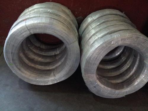
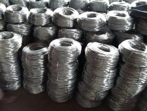
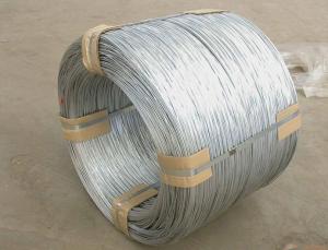
Electro Galvanized Wire:
Electro galvanized wire ranging from BWG8# to BWG16# is the mostly used for customers. We also offer thinner galvanized wire down to BWG5# or up to BWG28# upon customers specific order. Single coil package for electro galvanized wire can be as small as 10 kg and up to maximum 1000 kg per coil.
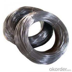
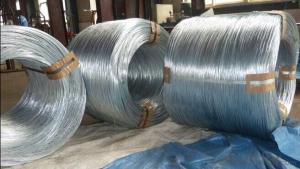
Electro Galvanized Wire Processing & Features:
This kind of galvanized wire is made with choice mild steel, through wire drawing, wire galvanizing and other processes. Electro galvanized wire has the characteristics of thick zinc coating, good corrosion resistance, firm zinc coating, etc.
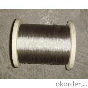
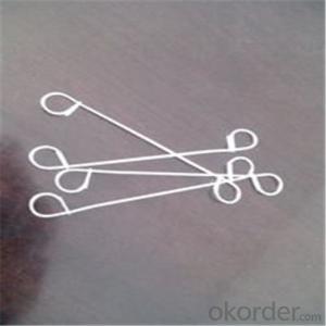
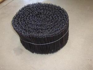
Forms of Supply:
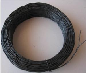
Electro galvanized wire can be supplied in the form of coil wire, spool wire or further processed into straightened cut wire or U type wire.
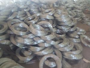
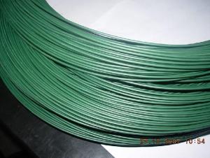
Electro galvanized wire applications:
Electro galvanized wire is mainly used in construction, express way fencing, binding of flowers and wire mesh weaving.
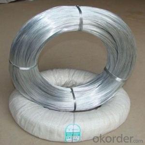
Electro galvanized iron wire, electro galvanized steel wire, electro galvanized wire.
BWG6-22 5.0MM-0.8MM.
Zinc coat: 5-25g/m2.
Tensile strength: 35-120kg/mm2.
ZINC COATING TABLE
SIZE mm | (g/㎡)Min. zinc coating | |||||||
A | AB | B | C | D | E | F | ||
A1 | B2 | |||||||
≤0.25 | 18 | 15 | 12 | 5 | ||||
〉0.25-0.40 | 25 | 20 | 12 | 5 | ||||
〉0.40-0.50 | 25 | 20 | 15 | 8 | ||||
〉0.50-0.60 | 25 | 20 | 15 | 8 | ||||
〉0.60-0.80 | 20 | 15 | 10 | |||||
〉0.80-1.20 | 25 | 18 | 10 | |||||
〉1.20-1.60 | 25 | 18 | 12 | |||||
〉1.60-1.80 | 100 | 70 | 40 | 30 | 20 | |||
〉1.80-2.20 | 105 | 80 | 50 | 40 | 20 | |||
〉2.20-2.50 | 110 | 80 | 55 | 40 | 25 | |||
〉2.50-3.00 | 120 | 90 | 70 | 45 | 25 | |||
〉3.00-4.00 | 100 | 85 | 60 | 30 | ||||
〉4.00-5.00 | 110 | 95 | 70 | 40 | ||||
- Q: I'm trying to use a stereo wire instead of a mono wire for an output from a circuit I've built. The problem is, the gold wire has been cut too short, and I'd rather not strip it back any further since I don't have a lot of cord to work with. Since there are three wires (red, white, gold - ground) can I use either the red or the white as output, and the remaining color for ground, or do I have to use the gold cable for the ground and let the remaining wire dangle (taped)?Thanks
- The gold wire is actually copper. It is braided and surrounds the red and white wires. It not only forms the common return for both the other wires, it is also a screen which eliminates unwanted pick up. The right channel signal appears between the red wire and the sceeen and the left channel signal appears between the white wire and the screen - which is usually grounded. If you use the red and white wires on their own you will probably get pick up on them. The screen really is necessary. If you have access to the screen at only one end (it sounds as if you might) then connecting the screen to whichever wire you choose to be grounded might be sufficient.
- Q: my husband is running wire to a hot tub, which uses a 220 plug. he is going to hook up a 30 amp breaker. what size wire should be used?
- If he does not know he had better leave it to a pro or you will get fried or burn the place down! GEEZ!
- Q: i want to install a new light in a old house.the problem is that there are three black wires coming out of he ceilng.the old light fixture has two black wires. two ceiling wires are connected to one fixture wire and the other ceiling wire i connected to he other fixture wire.i dont know which is the hot wire and which is the comon wire.also the new light has a ground wire ,2 blue wires and 2 white wires but, there is no ground wire coming out of the box. please help
- Seems to me you are dealing with an old knob and tube wiring system, not complicated. You probable have three cotton coated wires in the ceiling box, they used to be coded and now they're tarnished. Two of the wires are common or neutral and one live being fed from the switch. When you removed the old fixture two wires were connected to one side of the light fixture these are the common wires and one wire was connected to the other side of the fixture this is the live wire from switch. If you can't remember which was which, simply get a tick tracer this device senses a live wire and with the power off verify that you have no live in the ceiling, with power on try again, if you find one power it's as I have said and the remaining wires are common, if not call an electrician they won't charge that much to hang a light fixture and you'll have peace of mind. Good luck.
- Q: Wired car radio no sound powered on then wires crossed had to run red straight to battery. Then memory and ground crossed. Now nothing. Checked fuses radio fuse is bad. Will i also need a new wiring harness? Stereo Works fine when hooked up to battery charger.
- Could you rewrite your question and clear it up some. The red wire should go to the ignition on the existing harness in the dash. You were crossing all of those wires? Look at the diagram that came with the deck to know which wires go where. Typical pairs of wires (white and white w#x2F;black stripe or gray and gray w#x2F; black stripe) are for the speakers, red is for power(ignition) I think green is the signal wire and so forth. I don#x27;t know how your wires just get crossed like that? Did you splice them into the wrong ones in the dash?
- Q: Im cleaning up some of the wires in the engine bay and getting rid of ones i dont use. Right now theresthe pos side bat post runs down to the starter. From the starter there is a thicker wire and a skinny wire. In the thicker wire there is a wire that goes to the post on alternator. Both wires from starter run over to a relay maybe ithas a stud sticking out and has a wire that goes from the bottom of it to the fuse box. Im in middle of relocating the battery into the trunk so what wires can i eliminate and what wires have to go,to the battery?
- Yeah I hate to say it but moving the battery to the trunk is a bad idea. Especially if you don't know what all the wires are there for. Some are grounds others are hot. You switch them you will burn something up.
- Q: hi i recently installed new plug wires into my continental should i put shieldings on them?
- depends on what year the car is.did your old wires have shields?
- Q: I have a wire coming from the car battery positive terminal. It is 12v DC. I want to split this wire to two other wires. I cannot connect another wire to the positive terminal. Will splitting this wire cause the voltage to drop to 6v each wire? or will they pull a constant 12v each?
- Each okorder /
- Q: What's the best kind of wire to use that can stand being kilned?
- that really depends what you want to do and how high you are going to fire. Generally nichrome 80/20 wire should be OK until cone 9. Then there is Kanthal which will withstand even higher temperatures but is more expensive than nichrome. You could get either probably in electronics supply houses. If you do lowfire, maybe up to cone 06 or lower steel will probably be OK. The surface of the steel will oxidise and so get clearly thinner, keep that in mind. Generally your wire and the clay should not be in direct contact because they have different thermal expansion coefficients. Depends how rigid your wire is if it will lead to major damage to your piece. But if you wrap your wire with paper before you put clay around it it is probably OK as long as you don't enclose the entire thing with clay into a hollow space. But it also depends on what exactly you are trying to do, e.g. what kind of clay you are using. Mostly people use wire with clay for making beads. If that's what you are doing you can also look up bead making techniques.
- Q: want to get ready to solderis the fuzzy stuff the wire? or the shiny (positive green and negative red color) the wire? sorry i know its a noob questionlet me knowthanks
- wire is metal and metal is orange or silver . The fussy stuff is string
- Q: And i am unsure on how to wire the speakers. Do i just splice the wires from the speakers to the corresponding wires on the harness. P.S. It is not actually in a boat, it will be connected to a 12v battery.
- U JUST RUN THE HOT(RED) WIRE TO THE BATTERY. U ALSO MIGHT HAVE TO HOOK UP THE MEMORY WIRE(YELLOW WIRE) AND THE REMOTE ( SOLID BLUE) WIRE TO THE POSITIVE TERMINAL OF THE BATTERY AS WELL BEACAUSE SOME RADIOS WONT TURN ON WITHOUT THESE WIRES COONECTED. THE WHITE AND GREY WIRES ARE THE FRONT AND THE GREEN AND PURPLE ARE THE BACK SPEAKERS. YOU SHOULD GET THE WIRING HARNESS FOR THE WIRING IF ITS GOING IN A CAR LIKE A JEEP THEN ALL U GOTTA DO IS MATCH THE COLORS UP ITS EASY . BUT STRAIGHT TO A BATTERY DO IT THAT WAY JUST MAKE SURE U HAVE A GOOD GROUND.
Send your message to us
Electro Galvanized Wire BWG22 For Binding
- Ref Price:
-
- Loading Port:
- Tianjin
- Payment Terms:
- TT OR LC
- Min Order Qty:
- 5 m.t.
- Supply Capability:
- 1000 m.t./month
OKorder Service Pledge
OKorder Financial Service
Similar products


Hot products


Hot Searches
Related keywords

