
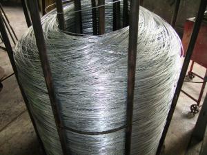
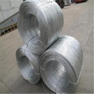
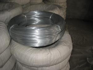
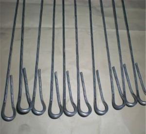
Hot Dip Galvanized Steel Wire For Wire Mesh And Cable Armouring
- Ref Price:
-

- Loading Port:
- Tianjin
- Payment Terms:
- TT OR LC
- Min Order Qty:
- 5 m.t.
- Supply Capability:
- 100 m.t./month
OKorder Service Pledge
OKorder Financial Service
You Might Also Like


Specifications
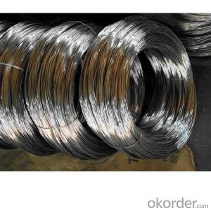
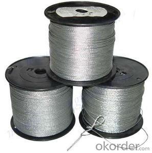
high tensile strength galvanized steel wire
Material:low carbon steel wire
Diameter:0.7-4.0mm
Zinc rate:40g-365g/s
Hot Dipped /Electro Galvanized Steel Wire
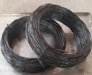
1.material:
The main materials of galvanized iron wire is iron wire, mild steel wire and carbon steel wire.
2.specifications
Diameter(mm) | Tensile Strength MPa | Weight of zinecoat g/m |
1.24-2.25 | 1340-1620 | 185-215 |
2.25-3.00 | 1310-1590 | 230 |
3.00-3.50 | 1290-1550 | 245 |
3.50-4.25 | 1290-1520 | 260 |
4.25-4.75 | 1290-1520 | 275 |
4.75-5.50 | 1290-1520 | 290 |
3.Wire diameter: 0.7mm-6.0mm
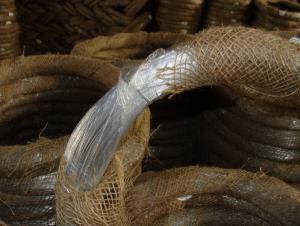
4.Process: Wire drawing, acid washing and rust removing, annealing and coiling
5.Feature: Excellent flexibility and softness
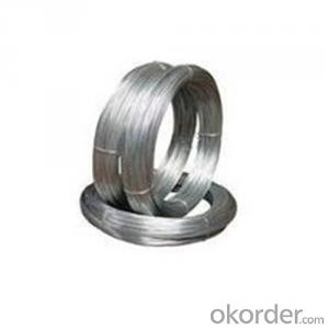
6.Zinc rate: 40g-365g/sqm.
7.Application: Extensively used in construction, handicrafts, woven wire mesh, express way fencing
mesh, packaging of products and other daily uses.
- Q: How is the line differ from a neutral and ground wires in a three prong plug?
- the bare wire is the ground and goes to the green lug == the black wire goes in the brass screw/lug=== and the white wire then goes in the silver/aluminum looking screw/lug === the purpose of the ground is to act as a safety net to prevent shocks and c
- Q: The power supply is at the fixture in this case. I have 2 black wires (1 is the hot, I connected the hot to the other black to continue to the switch. The other wires are 2 white wires, 1 red wire and 2 grounds. At the switch there are multiple wires, including 3 black wires, 1 red, 3 white and 3 ground. One of the black wires I know goes on to other fixtures in another room. My issue now is I cannot get my main fixture I was trying to change the switch on to work and don't know which wire to connect to the switch. Right now I have removed the switch completely so the other rooms lights will work. Here is how I have it set up now. At the fixture black to black, white to white, red capped 2 grounds capped together. At the switch area: Black (hot from the fixture) to 2 blacks, all 3 whites connected, red is capped, and grounds are together. Which wires do I connect to the switch to control the fixture and still allow the other rooms lights to work. HELP!
- The key is the red wire. At the switch junction, attach the red wire to one terminal of the switch. Combine all the black wires into one bundle and pigtail off a length of wire to attach to the other terminal on the switch. The black wires are now all constant hot, and the red wire is the switch leg going up to the fixture. The white wires should remain bundled by themselves. The bundle of ground wires can also be attached to the green ground terminal on the switch if one is present. At the fixture junction, bundle all white wires together and do the same with the ground wires. Attach the red switch leg to the black fixture wire. The remaining black wires in the junction should be bundled together to remain isolated from the fixture.
- Q: Am I able to do this? The wire burn the clay?
- if you're using a clay like the 3 main Sculpeys (original Sculpey, SuperSculpey, and Sculpey III), you will especially want to use wire inside them (or use other kinds of armatures) in any thin or projecting areas since those lines of polymer clay are brittle after curing in those kinds of areas
- Q: when wiring subs to different ohm levels, does is matter what kind of speaker wire you use to connect to the + and - terminals? i mean like gauge wise of the speaker wire and such.
- Too big of wire is just a waste of money. As Rick said, 12-16 is ideal for subs. 10 AWG would be the maximum size required.
- Q: at least 3 examples for wire and wireless......
- Wire simplex: Serial data from GPS to PC or autopilot using 2 wires. Wire, half duplex: Theatrical intercom, with push to talk buttons for each spotlight operator. Wire, full duplex: telephone. Wireless, simplex: infrared remote control for TV. Wireless, half duplex: walkie-talkie, family radio service, cb radio. Wireless, full duplex cellphone, cordless phone.
- Q: we need to know how an electrical wire is measured. When you say for example a stranded tw wire 2mm2 does it mean 2mm square or 2 square mm meaning the area of the wire? does the measurement or size indicated in the insulation includes the insulation itself when measuring the wire? how about a stranded wire? basically the question is please explain the size of thw or tw wire stranded or solid wire indicated on the insulation. And how it is measured. does the insulation included in the measurement or just the copper wire inside that is measured.
- strandings of the wires equal a gauge. ex: 7strands of 30gauge wire equals 22 gauge. gauge is a size of either a solid wire or smaller stranded wires to equal that size
- Q: im installing a line out converter on my 2006 avalnche and i need to know which wires go to the right and left rear speakers so i can install it, do you know which is wire goes to where?
- Avalanche Diagram
- Q: i got a fi bl 15dual 2 subwoofer. im wiring it down to 1 ohm.now for the problem. lets say im wiring the positive terminals together. am i suppose to wire it all with positive wire or can i also use negative copper wire? i used two positive wires and one negative wire to hook up the three positive terminals. is this bad? do i need to make all of them positive silver wires?
- Wire is wire. lol. There is no positive or negative wire. A wire can carry either a positive or a negative flow. So it doesn't matter whether you have the silver or black or whatever color wire running, just make sure you connect it correctly to the terminals and amp.
- Q: I have a 98' F-150 and need to add a 4 flat trailer wire connector to it. What all do I need to do? Is their a special connector?
- If it has an existing plug (6 or 7 Pin round) just buy an adapter. If the truck was equipped with a towing package but you do not have a plug of any kind look under the truck near the rear bumper you should find a bundle of wiring that is not connected to anything. this bundle should include the following colors of wires (red, blue, green, yellow, brown, black with a green line, and White). Go to Auto Zone ot Wal-Mart and get a 4 flat truck side kit. Strip and splice the wires together color to color. Green being your right turn signal, yellow- Left turn signal, Brown-Taillights/Marker lights, White-Ground. If the bundle of wiring is not there then you will need to find the wiring that goes to the tail lights on the truck and splice in to them. Splice into these wires using the same color code i just stated above with Scotch-Locks then for the White wire on the kit just put a ring connector and use a self tap screw to mount it to the frame of the truck or the tow hitch.
- Q: I'm trying to install a ceiling fan and I'm looking for some help given my home's wiring. I have a single light switch in the room, and here's what's coming out of the ceiling: 2 white wires, 2 black wires and a ground wire. It seems like a set of white and black originate from the same location (in both cases). My celing fan with light has a remote connection, so there's one black, one white and one ground wire coming from my fan to connect to the ceiling. Can someone let me know how to hook it up so the fan and light both work? Thanks in advance.
- if you have separated the wires from one another you have created a small problem which will require that you determine which pair are bringing the power in (line) You can buy a cheap 2-wire tester which us always a useful tool to have around. with the power on, carefully touch the the tester to one pair at a time (a black and white wire- don't let any of the wires touch each other, and the tester should light up. the other pair are running to the switch. note which pair is which. Have the switch extended out of the wall so that you can examine the wiring. Using wire nuts, ( the plastic screw-on caps) attach the hot black to the white wire of the non-hot pair and shove deep into the box out of your way...you are done with it.. that will deliver the power to the switch and now the black from the non-hot pair will bring it back to the fan becoming your new hot wire controlled now by the switch.. the switch should have the white wire and the black wire from the same pair attached to it..) the white wire from your remote receiver will attach to the white wire from ceiling box and the black and blue (light)wires from the receiver will connect with wire nuts to the newly established hot black. SWITCH AT WALL SHOULD NOW BE OFF. you can now continue the fan installation. Be mindful of the fact that the remote receiver slides into the space in the fan mounting bracket and there is very little room to get the receiver and all the connected wires in and under the canopy/cover. being as neat as posible with your wiring and wire placement is essential. good luck.
Send your message to us
Hot Dip Galvanized Steel Wire For Wire Mesh And Cable Armouring
- Ref Price:
-
- Loading Port:
- Tianjin
- Payment Terms:
- TT OR LC
- Min Order Qty:
- 5 m.t.
- Supply Capability:
- 100 m.t./month
OKorder Service Pledge
OKorder Financial Service
Similar products


Hot products


Hot Searches

