

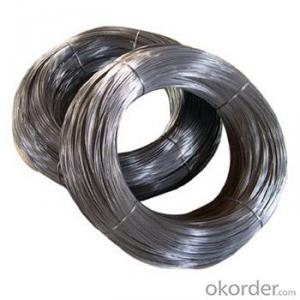
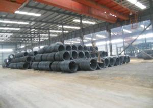
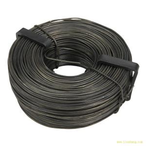
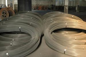
1.0/50 Steel Fiber from company CNBM China
- Ref Price:
-

- Loading Port:
- Tianjin
- Payment Terms:
- TT OR LC
- Min Order Qty:
- 1 m.t.
- Supply Capability:
- 10000 m.t./month
OKorder Service Pledge
Quality Product, Order Online Tracking, Timely Delivery
OKorder Financial Service
Credit Rating, Credit Services, Credit Purchasing
You Might Also Like


Quick Details
Place of Origin: Tianjin, China (Mainland)
- Model Number: 1.00
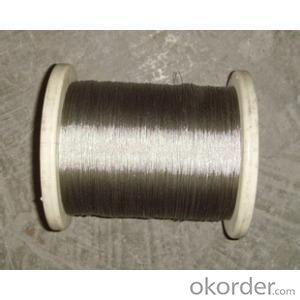
Material: Steel
Production Process: Cold drawn
Fiber Lengh: 50
Type: 1
Compressive Strength: >1200MPa
Aspect ratio: 50
Standard: ASTM A820M-11
Section Shape: Circular
Application: Concrete Reinforcement
- Product Application: Tunnel
Packaging & Delivery
| Packaging Details: | 20 kg/Bag,50 bags/Pallet or 1,000kg/ Bulk Bag |
|---|---|
| Delivery Detail: | 1 Month |
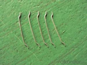
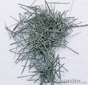
Product Description
| Diameter | 1.00 | mm | 0.04 | in |
| Length | 50.00 | mm | 1.96 | in |
| Aspect Ratio | 50 | |||
| Tensile strength | 1200 MPa | |||
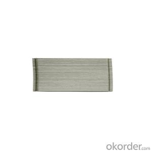
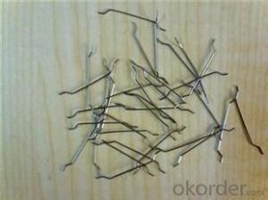
| Type | Cold drawn Steel Fiber | |||
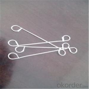
| End | Hooked-end Steel Fiber | |||
| Glued/Loose | Glued Steel Fiber | |||
| Bending Angle | 45°(min.30°) | |||
| Usage & Performance | Floor:Trafficked areas and Industrial floors | |||
| Shotcrete :Slope stabilization and Final lining | ||||
| Precast concrete:Pipe and Railway sleepers | ||||
| Packing | Standard Export Pallet Packing | Bag Packing | 20 kg/Bag,50 bags/Pallet | |
| Bulk Packing | 1,000kg/ Bulk Bag | |||
| Loading Quantity | 20’GP | 20-25 Tonne/Tonnes | ||
| 40’GP | 25-27 Tonne/Tonnes | |||
| 40’HQ | 25-27 Tonne/Tonnes | |||
| MOQ | 1 kg for trial order | |||
| Supply Ability | 10,000 Tonne/Tonnes per Year | |||
| Payment Terms | T/T or L/C at sight | |||
| Delivery Time | Within 15 days after receiving deposit or original L/C at sight | |||
| Certification | ISO9001:2000, CE, | |||
| Product | Diameter | Length mm/in | Aspect Ratio | Type | Packing |
| G-6030 | 0.5 mm (0.0197 in) | 30 mm (1.1811 in) | 60 | Glued | 20 kg/Bag, or 1,000kg/ Bulk Bag |
| G-6535 | 0.55 mm (0.0217 in) | 35 mm (1.3780 in) | 65 | Glued | 20 kg/Bag, or 1,000kg/ Bulk Bag |
| G-6035 | 0.6 mm (0.0236 in) | 35 mm (1.3780 in) | 60 | Glued | 20 kg/Bag, or 1,000kg/ Bulk Bag |
| G-8060 | 0.75 mm (0.0295 in) | 60 mm (2.3622 in) | 80 | Glued | 20 kg/Bag, 50 bags/Pallet |
| G-6060 | 0.9 mm (0.0354 in) | 60 mm (2.3622 in) | 60 | Glued | 20 kg/Bag, 50 bags/Pallet |
| G-6030 | 0.5 mm (0.0197 in) | 30 mm (1.1811 in) | 60 | Loose | 20 kg/Bag, or 1,000kg/ Bulk Bag |
| G-6535 | 0.55 mm (0.0217 in) | 35 mm (1.3780 in) | 65 | Loose | 20 kg/Bag, or 1,000kg/ Bulk Bag |
| G-6035 | 0.6 mm (0.0236 in) | 35 mm (1.3780 in) | 60 | Loose | 20 kg/Bag, or 1,000kg/ Bulk Bag |
| G-8060 | 0.75 mm (0.0295 in) | 60 mm (2.3622 in) | 80 | Loose | 20 kg/Bag, 50 bags/Pallet |
| G-6060 | 0.9 mm (0.0354 in) | 60 mm (2.3622 in) | 60 | Loose | 20 kg/Bag, 50 bags/Pallet |
- Q: Hi there,I have a very old house which only has 2 wires (1 white, 1 black) coming out of the wall.The ceiling fan / light has 2 red wires, 1 black, 1 green.What is right way to wire for this to operate?Thanks,
- Most fans have a wiring schematic and this will tell you how to wire it. Normally black is the power, green is a ground, which you don't have, and as for the red wires I'm not sure. Is this a new fan or one that has been used before. In the USA we have a white wire which is a neutral. I'm puzzled about the two red wires, these may have been added at a later date. If your in a country that has 240 volts then this may be an explanation. Regards, Dale
- Q: I am doing wiring in my shed on preexisting light fixtures and outlets. the wiring that was disconnect from that carried the electricity to it. What I am trying to do is have all the light fixtures work of an extension cord. I have another extension wire connected to that with the +, - and 0 showing. The fixtures have 3 wires coming out of them what I think to be the power in, power out, and switch. On the fixture on the end I connected my extension cord thing and it work, BUT only that one. The rest of the fixtures did not work, I do see anything wrong. What I thought was that I was connecting to the switch wire so I changed it and it just buzzed with blue light. What is going on?
- the rest of your light fixtures maybe wired through a switch. you would have to hook your extension cord to the switch but you also need to connect the common neutrals and grounds to the cord as well.
- Q: Where is itI have a 1996 Honda Accord with a pioneer deh-p6400 head unit. I tried to install an amp. Held the ground to soem metal and tried to get it to turn on. I tried the power antennae wire and it didnt' work. Nothing seems to work. I dont want to splice any wires or anything
- The pioneer head unit should have a 'remote' wire that is energized while the head unit is turned on. you could also tap a fuse that is energized while the key is in the on position, such as the windshild wipers, or the pwr window fuse. Then the amp will come on whenever the kar is turned on.
- Q: I spliced the stereo wires to the adapter to plug into my car. there's 2 extra orange wires in the adapter. There orange it says there for illumination and the dimmer. What should I do with them? Did I get the wrong one?
- You should have bought a radio adapter for your car! Splicing the cables is not a good idea! You can get a Radio adapter which joins the connector from the radio to the cars radio wiring!
- Q: I recently purchased a 1-wire alternator and I'm not sure what to do with the wire harness that was on my stock alternator. Also not sure what the three wires on it go to. Can anyone experienced in alternator wiring tell me what these wires do and if it is ok to leave them unhooked?
- Connect the existing larger wire to the stud with the 7/16 nut.That goes straight to the battery+. Use a test light to find the smaller wire that goes hot with the ignition on.That goes to the terminal marked f or field.That turns the alternator on and off so it doesn't drain the battery when the engine is off. The other terminal on the alternator is to the gauge or light.
- Q: I no longer have enough 0 gauge wire would it be bad to use 0 gauge power wire to the amp and 4 gauge wire to ground the amp?
- Umm well it really depends on how much power you are running through it. If your amp is only about 200-400 watt rms, then you should be fine with a 4awg ground. However, if your rms is higher than 400 you seriously need to consider getting some bigger gauge wire.
- Q: remote 2 wires for power black - white also 3 wires to goto fan/light ? white - black - red
- wire it black to black white to white. original wiring could be wrong. please better description. for light kit red or blue should connect to that. dont forget grounding wire even though white wire polarizes
- Q: What are those strange ball-like things that are on some electric/telephone wires? I think they're on electric wires. I've always wondered.
- they are there so you can see the wires better.... that way planes helicopters etc. dont run into them
- Q: The question is can i complete a ac circuit if i connect a live from one wire to a neutral from another.
- hire an electrician dont get yourself electricuted hun <3
- Q: like can u use home power wire that is 4 gauge rather then getting the car power wire
- Home okorder /... (spanky, well trying to run solid wire in a car would be a real task! lol) And, 4 gauge can handle more than 95 amps.
Send your message to us
1.0/50 Steel Fiber from company CNBM China
- Ref Price:
-
- Loading Port:
- Tianjin
- Payment Terms:
- TT OR LC
- Min Order Qty:
- 1 m.t.
- Supply Capability:
- 10000 m.t./month
OKorder Service Pledge
Quality Product, Order Online Tracking, Timely Delivery
OKorder Financial Service
Credit Rating, Credit Services, Credit Purchasing
Similar products


Hot products

Hot Searches
Related keywords

