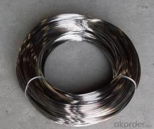
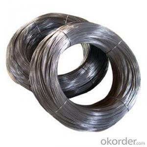
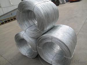
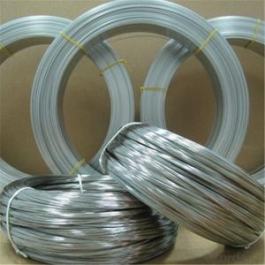
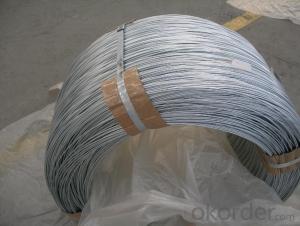
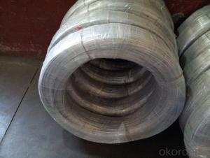
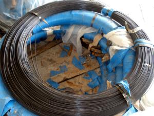
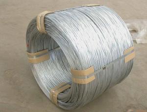
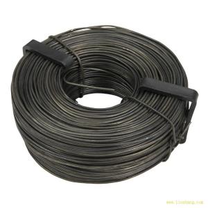
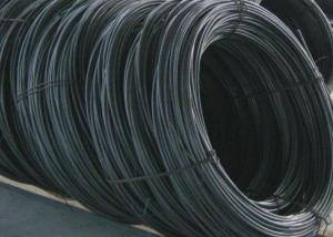
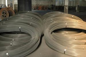
Electro Galvanized Iron Wire For Chain Link Fence
- Ref Price:
-

- Loading Port:
- China Main Port
- Payment Terms:
- TT OR LC
- Min Order Qty:
- -
- Supply Capability:
- -
OKorder Service Pledge
OKorder Financial Service
You Might Also Like


Packaging & Delivery
| Packaging Detail: | Spool, Reel, Coil, |
| Delivery Detail: | 2~5weeks |
Specifications
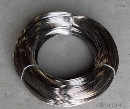
1) Bright and smooth surface
2) Different coil weight available
3) Small tolerance on wire diameter
4)ISO approved
Electro Galvanized Wire
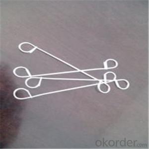
1)Application: | This kind of industrial wire is mainly used in construction, making of wire nails and wire ropes, express way fencing, binding of flowers and wire mesh weaving. |
2) Material: | Carbon steel wire, mild steel wire |
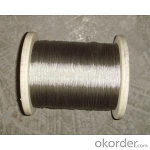
4) Surface: | Electro Galvanization |
5)Diameter: | 0.28mm~4.00mm |
Tensile strength | 320-500MPA |
6) Technical Info: | Surface: hot-dipped zinc coated Tensile strength:340-500 N/mm2 for all sizes |
7) Packing: | 2kg~500kg, in small coils, big coils and on spool or drums |
9) All can be produced according to customers’ actual requirement. | |
- Q: so im lost in how i should wire my subs. I have two subs that i need to wire both are 2 ohms 400 watts i don't know if i should wire them parallel or series if you can help me out that would be great!
- usually all sub wiring is the same, youll have the rca cables and antenna wire comming from the radio to the amp, power and ground wire going from amp to battery and ground, and than should have 2 wires coming off each sub to the amp, im guessing thatd be parallel, if you wire in series, so like use 2 wires and splice off to each sub, so 2 wires off the amp powering each sub you would up the ohms and put a too much of a load on the amp, people only wire in series when they have too many subs and not enough outlets on the amp, good luck
- Q: how to wire the alternator for a 77 mustang
- the big black wire is you charging wire should go in the battery side of the starter relay the STA post in the alternator goes to terminal S on the voltage regulator the FLD post goes to terminal F on the voltage regulator and there might be a ground wire next to the FLD post on the voltage regulator wire A+ goes to the battery side of the starter relay and wire I goes to the charging indicator light I'm not sure were the voltage regulator is in a mustang but its a square metal box i think it might be on the radiator support or inner finder
- Q: Two wires are placed parallel to each other. What would be the effect of passinga) upward current through both wiresb) an upward current throgh one wire and a downward current through the other.Explain.
- a) When the currents through both the wires are in the same direction, the magnetic field due to each midway between them, by right-hand thumb rule, will be in opposite directions. This will result in attraction between the wires. b) When the currents through both the wires are in the opposite directions, the magnetic field due to each midway between them, by right-hand thumb rule, will be in the same direction. This will result in respulsion between the wires.
- Q: From one website I withdraw thru bank wire its 50 dollar fee.What ranges are it for bank wire? Internationally from private person to business.
- The bank wire fee varies depending on the individual policies of the bank. Some banks charge for wiring, or receiving. Others charge of international wires. Still others may waive wire fees if you have a special relationship with the bank, such as a Premier Customer, or a senior citizen, etc. Check with your bank.
- Q: Quick question with hopefully an easy answer. I had a dimmer switch go bad on a light in a dining room. I bought a new switch and put it in. It was working fine, so I thought, then I noticed that when the dining room light is off, the dimmer works on everything else on the circuit, for example outside lights, hall lights, etc. I can dim all of those things when this switch certainly didn't do that before. Also, if the dining room light is on, all of the other things on the circuit I mentioned before do not work at all. I've obviously incorrectly wired the switch somehow, any thoughts on what I did incorrectly and how to fix?
- The problem is going to be the THREE black wire connections. You have to identify the INPUT POWER wire to the box, the DINING ROOM wire and the 'EVERYTHING ELSE wire. Separate the three black wires. Measure between each black wire and the white wire bundle. The black wire that has 120 vac on it is your INPUT POWER wire. Momentarily connect the black INPUT POWER wire to each of the other two black wires. One of those other two black wires will light up the dining room light. It is that black wire that gets connected to the LOAD connection on the dimmer switch. The other black wire is your EVERYTHING ELSE wire. Connect that wire to the INPUT POWER wire. Run a pigtail from those two wires to the LINE connection of the dimmer switch.
- Q: I am trying to hook up my motorcycle turn signals but am having trouble with the wiring. Off of each signal stem comes a red wire (positve) and black wire (negative). Then coming form my bike I have a purple wire, blue wire, and green wire. I was messing around with the connections and was able to get all my signals to light up, but not in the fashion i need, like blinking correctly. Any suggestions? Do I need to split the wires? Does one wire go to the left signal and one to the right?
- Does the flasher work? Are you using two filament bulbs? The green wire is a ground. The blue and purple sound like HD wiring, one is for blinkers, and one for running lights.
- Q: (PRIOR TO READING, I SUGGEST YOU LOOK AT THE IMAGES AS IT WILL MAKE THINGS A WHOLE LOT EASIER TO UNDERSTAND)I purchased 2 neons from Repco. That run off your cigerette lighter with an adaptor. They worked fine, until my friend got in my car, and accidentally dropped something on the adaptor which caused it to malfunction, and bam, my in-car neons (placed up under the dash, near where your feet rest) went out.
- wire is wire. If it really is silver then theoretically it should conduct electrcitiy better than copper. But that doesn't really matter much. wire is wire. all it needs to be able to do is carry the electrical current. If wiring truly is your problem, then that will work fine.
- Q: exact wiring
- 1995-96 Dodge Dakota Alarm, Remote Starter, Keyless Entry Wiring Information Constant 12V+ Pink/Black Ignition Switch Harness Starter Yellow Ignition Switch Harness Ignition Dark Blue Ignition Switch Harness Ignition 2 Black Ignition Switch Harness Accessory Black/Orange Ignition Switch Harness Tach Gray Coil Neutral Safety Wire Brown/Yellow Driver's Side of Trans. Brake Switch White or White/Tan Brake Switch Trunk Pin n/a Parking Lights Black/Yellow Light Switch Head Lamp Light Green Light Switch Hood Pin n/a Door Trigger Yellow (-) Driver's Pin Switch Door Lock Orange/Purple Driver's Kick Panel Door Unlock Pink/Purple Reverse Polarity Horn Wire Dark Green/Red (-) Fuse Panel Windows Up LF=Light Blue, RF=Brown/White Windows Down LF=White, RF=Purple/White
- Q: how do i connect ignition wire from fuse box to cd player?
- your wanting to run a wire from your cd player to the fuse box?, ok, take a piece of covered wire, hook it to the hot wire of your cd player, run it down to the fuse that says radio, it should play on accessories and while your driving.
- Q: i have an amp (sony xm 2002gtr) that says it requires 4 gauge wire..but they cost $100+ and i have plenty of 8 gauge wires. can i use two 8 gauge wires as a substitute for one 4 gauge wire?and also, i have my capacitor grounded to unpainted metal of my car AND the ground port of my amp..is that incorrect?
- Two 8-gauge wires combined are equal to a 5-gauge wire, but that should be close enough for that amp. Make sure each wire has its own fuse near the battery; 40-amp fuses would be a good choice. If you capacitor is connected to ground, and your amp is grounded, then you don't really need a wire between the capacitor's ground terminal and the amp's ground terminal. It doesn't hurt anything, though. If the only ground wire at the amp is the one that runs to the capacitor, then you're better off connecting the amp ground directly to chassis metal.
Send your message to us
Electro Galvanized Iron Wire For Chain Link Fence
- Ref Price:
-
- Loading Port:
- China Main Port
- Payment Terms:
- TT OR LC
- Min Order Qty:
- -
- Supply Capability:
- -
OKorder Service Pledge
OKorder Financial Service
Similar products


Hot products

Hot Searches
Related keywords

