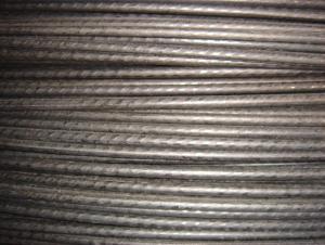
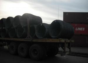
PVC Coated Steel Wire Rope
- Ref Price:
-

- Loading Port:
- China Main Port
- Payment Terms:
- TT OR LC
- Min Order Qty:
- -
- Supply Capability:
- -
OKorder Service Pledge
Quality Product, Order Online Tracking, Timely Delivery
OKorder Financial Service
Credit Rating, Credit Services, Credit Purchasing
You Might Also Like


Quick Details
Steel Grade:steel
Standard:AISI, ASTM, BS, DIN, GB, JIS
Wire Gauge:5/32 inch to 7/16 inch
Place of Origin:Chongqing, China (Mainland)
Type:Galvanized
Application:Steel Wire Rope
Alloy Or Not:Non-alloy
Special Use:Cold Heading Steel
Model Number:CHPVC20101012
Packaging & Delivery
| Packaging Details: | Wooden Spool,Plastic Spool |
|---|---|
| Delivery Detail: | 20days. |
Specifications
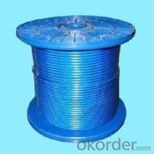
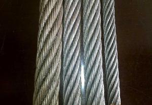
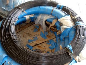
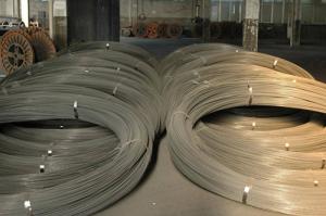
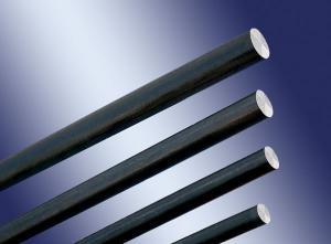
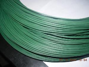
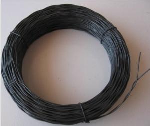
PVC Coated Steel Wire Rope
Available in Different Sizes
ISO9001:2008 Cert.
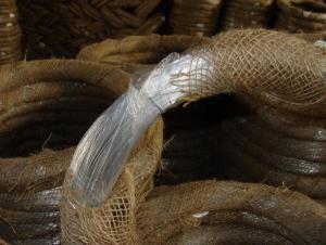
PVC coated steel wire rope and stainless steel wire ropes
Din standard: 7 x 7, 7 x 19 available
Diameter range from 5/32 inch to 7/16 inch
In various colors, transparent or nontransparent
- Q:Given following setup of three wires in the plane of the page with I1 = 1.3 A (to the right), I2 = 3.4 A (to the right), I3 = 4.5 A(to the left) and each wire is separated by 3 m.I'm completely lost, I need to..1. What is the direction of the magnetic field at wire 3 due to wires 1 and 2?2. What is the direction of the force on wire 3 due to wires 1 and 2?Any help would really be appreciated! Thanks!
- I assume that those wires are sitting parallel 3 m apart from one another. 1. The magnetic field around a wire forms concentric circles around the wire. Wire 1 and Wire 3 are parallel so when you draw a concentric field line around Wire 1 with radius 6 m, you get a magnetic field line passing Wire 3 at a right angle. And a concentric field line around Wire 2 with radius 3 m passes Wire 3 at a right angle. Both magnetic fields have the same direction because the current in both wires flows in the same direction (to the right). Using the right-hand rule, you can find that the magnetic field at wire 3 due to Wire 1 and Wire 2 goes into the page. Ans: Into the page 2. The force on a wire can be calculated in the following manner: I X B * L. Here I is the current on Wire 3, B is the magnetic field due to Wire 1 and Wire 2, L is the length of Wire 3, and X is the cross product operator. So I cross B would give the direction of the force. Now use the right-hand rule, I cross B will give the force direction pointing down. This means the force due to the magnetic field would repel Wire 3 from Wire 1 and Wire 2. Ans: The force on Wire 3 due to Wire 1 and Wire 2 would repel Wire 3 from them.
- Q:Having some trouble wiring fixture it seems to just stay on with the switch doing nothing.. here's the deal I have three different wires coming from ceiling power in, power out, and I believe switch.. there was a priovious light there so I know its correct just don't what wires go with what all help will be appreciated thanks
- Identify which wire goes where. The power in and the power out and the switch get confusing to anyone. In most cases they are all wired together and a jumper is used to wire the light. Except the return wire from the switch which is connected to the light. For a wire system using NM cable (romex) the power in is wired to the switch, the white in the switch cable is marked with black tape at each end and it is connected to the black of the power in cable the black from the switch is wired to the light, the rest of the wires are made up color to color and a short jumper is used from the whites to the light.
- Q:Some states allow the use of aluminum wire in houses in place of copper. If you wanted the resistance of your aluminum wire to be the same as that of copper, would the aluminum wire have to have a greater diameter than, smaller diameter than, of the same diameter as the copper wire? Calculate the thickness ratio of aluminum to that of copper.
- The resistivity of copper is ρ_Cu = 1.72 x 10^(-8) ohm - meters, whereas that of aluminum is ρ_Al = 2.82 x 10^(-8) ohm-meters [1]. Assuming that the wire runs are the same length L, the resistance in the aluminum wire will be R_Al = ρ_Al * L/A_Al, where A_Al is the cross-sectional area of the aluminum wire. The resistance in the copper wire will be R_Cu = ρ_Cu * L/A_Cu. If we want the same resistance in both wires, we require R_Cu = R_Al: ρ_Cu * L / A_Cu = ρ_Al * L / A_Al A_Al / A_Cu = ρ_Al / ρ_Cu. Since the resistivity ρ_Al of aluminum is higher, the aluminum wire must have a larger cross sectional area to yield the same resistance. To make this precise, suppose the wires are cylindrical. Then the cross sectional area is π(R_Al)? for the aluminum wire and π(ρ_Cu)? for the copper wire: π(R_Al)?/π(ρ_Cu)? = ρ_Al / ρ_Cu R_Al/R_Cu = √(ρ_Al / ρ_Cu) = √(2.82/1.72) = 1.28 The aluminum wire must be 28% thicker than the copper wire in order to provide the same resistance.
- Q:my radio was stolen i'm trying to put in a old radio in but when someone stoled my radio they cut the wires so now i can't tell what go,s where can someone please help? it's a ford f150 pu trck w/ 4 speakers i just need the wire color codes to hook-up,plus thy stole the manal to the trck too. please help.ty
- You might have to go to a speaker shop and they have a little wire gadget there which tells them which wires are what. Don't know if you'll have to pay though or not. You might be able to buy one yourself.
- Q:I am wiring a sony xplod amp up in my car and need to know what the skinny blue wire goes to. Any help would be appreciated.
- its the remote wire. it goes from your amp to the back of your stereo deck. if you have an aftermarket deck ( which i would hope you do) there will be a wire labeled that says remote wire. connect the blue wire with that wire behind the deck. the whole purpose of the wire is to tell the amp to turn on and off with the car.
- Q:Wires in the dash*Radio constant*Radio Switched*Radio illumination**please match these up with the options below**Wires on the stereo itself*Dashboard Light Dimmer Switch*Amplifier Remote or Power Antenna (Positive +)*(fuze) yellow memory (negative -)*(fuze) red 12v (positive +)if someone could please help that would be great-since the wires were replaced i cant go by color
- Car radio wire constant to stereo yellow memory. Car radio wire switched to stereo red 12v positive. Car radio wire illumination to stereo Dashboard Light Dimmer Switch. Don't forget to ground the black wire on the unit to the ground wire from the car harness. An extra ground strap to the chassis is a good idea also. If you don't have an amp or a power antenna, cap off the blue Remote/Antenna wire.
- Q:Or can stranded wire of the same gauge be subsitituted for solid wire without any consequences? The reason I ask is because its for a massive 4kJ capacitor discharge circuit, and I need all the energy delivered to the power coils im using, cant afford to have much leakage inductance.
- Stranded wires have slightly higher inductance than solid wires, but this is noticable only on transmission lines and larger conductors. if you are only using a short conductor, i don't think the inductance of the wire will affect the system, unless the wire is coiled.
- Q:i am installing a headunit, i connected all the wires the match, but i have some left over that i am confused about. from the wires that plug into the radio there is the antenna wire, the remote wire, and the ground with a washer to screw it down, and from the other is set of wires is a solid orange wire, which i have no idea where it goes to. so i connected the remote to the orange wire and didn't hook up the antenna to anything, and bolted down the ground wire. I'm wondering why i have 2 ground wires, and what the orange wire is and what do i connect to it?
- The orange wire may be an illumination wire that controls the illumination or brightness of the head unit's lights when the car's headlights are turned on. You have two grounds because one is a chassis ground used to ground the metal frame on your head unit to the car's ground. Your head unit may or may not have an input for the illumination wire, in which case you need to remove it. I would also ground the head unit's frame using the second ground wire. Try looking online for the pinouts for your particular car's factory head unit. This will take the guesswork out of the install.
- Q:The power supply is at the fixture in this case. I have 2 black wires (1 is the hot, I connected the hot to the other black to continue to the switch. The other wires are 2 white wires, 1 red wire and 2 grounds. At the switch there are multiple wires, including 3 black wires, 1 red, 3 white and 3 ground. One of the black wires I know goes on to other fixtures in another room. My issue now is I cannot get my main fixture I was trying to change the switch on to work and don't know which wire to connect to the switch. Right now I have removed the switch completely so the other rooms lights will work. Here is how I have it set up now. At the fixture black to black, white to white, red capped 2 grounds capped together. At the switch area: Black (hot from the fixture) to 2 blacks, all 3 whites connected, red is capped, and grounds are together. Which wires do I connect to the switch to control the fixture and still allow the other rooms lights to work. HELP!
- The key is the red wire. At the switch junction, attach the red wire to one terminal of the switch. Combine all the black wires into one bundle and pigtail off a length of wire to attach to the other terminal on the switch. The black wires are now all constant hot, and the red wire is the switch leg going up to the fixture. The white wires should remain bundled by themselves. The bundle of ground wires can also be attached to the green ground terminal on the switch if one is present. At the fixture junction, bundle all white wires together and do the same with the ground wires. Attach the red switch leg to the black fixture wire. The remaining black wires in the junction should be bundled together to remain isolated from the fixture.
- Q:How doI wire a ceiling chain light to wall switch? I want to stop using the chain to turn the light on and off. I hane already installed the wall switch and the wiring in the box but not sure how to connect the wiring in the box to the ceiling light wiring.
- intreped said it well but i want to know how did you run the wire through the wall switch . hopefully you ran it direct with the switch breaking the hot wire . so you will have one black and one white wire . before you hook it up use a lamp to make sure you have the right wires . and you don't have to worry about polarity the fan has forward and reverse and the light buld dos not care.
1. Manufacturer Overview |
|
|---|---|
| Location | |
| Year Established | |
| Annual Output Value | |
| Main Markets | |
| Company Certifications | |
2. Manufacturer Certificates |
|
|---|---|
| a) Certification Name | |
| Range | |
| Reference | |
| Validity Period | |
3. Manufacturer Capability |
|
|---|---|
| a)Trade Capacity | |
| Nearest Port | |
| Export Percentage | |
| No.of Employees in Trade Department | |
| Language Spoken: | |
| b)Factory Information | |
| Factory Size: | |
| No. of Production Lines | |
| Contract Manufacturing | |
| Product Price Range | |
Send your message to us
PVC Coated Steel Wire Rope
- Ref Price:
-
- Loading Port:
- China Main Port
- Payment Terms:
- TT OR LC
- Min Order Qty:
- -
- Supply Capability:
- -
OKorder Service Pledge
Quality Product, Order Online Tracking, Timely Delivery
OKorder Financial Service
Credit Rating, Credit Services, Credit Purchasing
Similar products
New products

Hot products
Related keywords

