

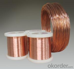
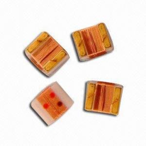
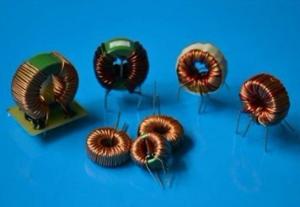
Low Frequency Copper Wire Only Chock Coil
- Ref Price:
-

- Loading Port:
- China Main Port
- Payment Terms:
- TT or LC
- Min Order Qty:
- 3000 Pieces pc
- Supply Capability:
- 300000 Pieces per Month pc/month
OKorder Service Pledge
OKorder Financial Service
You Might Also Like

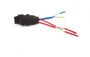

low frequency chock coil
1.Good quality and low price
2.deliver the goods on schedule
3.Radial Fixed Leaded Inductors with Inductance ranging from 0.30uH to 100mH.
4.ROHS compliance.
5.Remark:we can produce it according client's requirement
Our products have gained the international certifications, such as CQC, CE, RoHS, UL and so on, from internationally powerful authorities. We have got ISO9001 certificate. We promise to offer the best products to our clients. We look forward to cooperating with all friends for more mutual benefits.
- Q: Consider the following statements:(1) The current in the inductor cannot change suddenly.(2) The voltage across a capacitor cannot change suddenly.Now, my confusion is in the following question.
- Your picture just didn't come across on my system, so your question is a bit confusing. Yes, the properties of inductance and capacitance are almost exactly opposite each other, The important factor is TIME. FIRST, think in DC voltage mode. With a capacitor, if you present a sudden change of voltage across it, it appears as a short circuit -- but only for a short period of time. as the capacitor charges the resistance increases, until it presents an infinite resistance. The inductor, on the other hand respond oppositely. If you present a sudden change in voltage across an inductor, it present an open circuit -- but only for a short period of time. As the inductor charges it eventually presents no resistance to the voltage. NOW think in teh AC mode TIME is related to FREQUENCY. If your place an inductor and a capacitor in parallel with each other, you will develop what is known as a TUNED CIRCUIT. You will soon learn the formulas for what frequency is effected, given a capacitor and an inductor. IF you place a tuned circuit in the positive feedback loop of an amplifier, you will make what is know as an OSCILLATOR. This forms the basics of a radio or television system. The tuning of the circuit determines what channel you receive.
- Q: I got this wrong on my quiz, can someone show me how to do this?
- With the switch closed a long time the initial current in the inductor is Is+Vs/R1. The voltage across the inductor and the cap is 0. When the switch opens you have 2 independent problems. The voltage source and 2 resistor can be replaced by the Thevenin equivalent which is a voltage of Vs*R2/(R1+R2) and a resistance of RthR1*R2/(R1+R2). Now this is a simple RL circuit with an initial condition. The second circuit is a simple RC circuit.
- Q: A current in a 100microH inductor is known to be i(L) 20te^-5t for t 0A) Find the voltage across the inductor for t0. (Assume the passive sign convention)B) Find the power (in microwatts) at the terminals of the inductor when t100ms.C) is the inductor absorbing or delivering power at 100ms?D) Find the energy (in microjoules) stored in the inductor at 100ms.
- I don't have time to check the work, but here is the general idea. i(l) integral [v(t) dt], in this case, for t0 i 20te^-5t is given A) e(t) voltage across the inductor Ldi/et L20[ e^-5t(dt/dt) + t d(e^-5t)dt] L20[e^-5t + t(-5e^-6t)] (20 e^-5t)(1 - 5te^-t) B) Power e(.1) times i(.1) C) Absorbing, since e(.1) is still positive D) E (1/2) Li(.1)^2
- Q: Find the equivalent inductance for each of the series and parallel combinations
- It's the same as parallel and series resistors. 1) has 2H in series with 2H, making 4H, in parallel with 12, making 3, which is in series with 2, making 5 total. 2) Re the wire, it shorts out the 6H and the 3H inductors, so that leg just has 18H. Other leg has 10 and 15 in parallel, equivalent to 6H. In series with 3, that makes 9H. so you have 9 in parallel with 18, and that combo in series with 1 .
- Q: A fixed inductance L 1.07 ?H is used in series with a variable capacitor in the tuning section of a radio telephone on a ship. What capacitance tunes the circuit to the signal from a transmitter broadcasting at 6.90 MHz?answer in pFhow to solve this would be great :) a few step by steps maybe Thanks!
- The Physics communicate board, as at present constituted, is so heavily greater advantageous than the Astronomy and area communicate board. AS has a tendency to be exceptionally gentle. multiple i. Grade college homework, ii. Hoaxes (2012 stuff), and iii. Trolls surfing for interest. even regardless of the undeniable fact that homework help is annoying, on the least it somewhat is serious. which you will possibly have the potential to frequent self-clear out to seek for out questions that present day somewhat a wager and a questioner who's appreciative. there has been communicate among the aficionados of bobbing up a considerable Physics and Math communicate board. however the known consensus replace into that it would even regardless of the undeniable fact that be full of homework questions and direct mail trolls, and Y!A might now not be keen on the belief thinking what Y!A needs is site visitors.
- Q: If the current through the inductor drops from 110mA to 50mA in 13useconds? u is micro I think?Any ideas?Thanks
- The back emf generated by the collapsing magnetic field is given by . ? (-) L.di/dt L self inductance (H) di/dt rate of change of current (A/s) di/dt (110-50)mA / 13μs 60^-3A / 13^-6s 4.62^3 A/s ? (-) 12.0^-3H x 4.62^3A/s . . ?? (-) 55.40 V (- sign indicating a back emf)
- Q: I have 2 answers in terms of Joules, but not sure which one is correct.
- At DC the current through the inductor will be 3*4/62 amps. The energy is .5*L*I^2.5*.5*2^21 Joule.
- Q: 1. 12J2. 31J3. 16J4. 20JPlease explain further
- The standard formula for energy stored in an inductor is: E ?LI? . . ? x 2 x 4? . . 16J
- Q: A 3 H inductor with a resistance of 7 ohms is connected to a 12 V battery with negligible internal resistance. What is the current through the inductor 0.5 seconds after the battery is connected?
- Consider the inductor with its internal resistance to be like a perfect inductor (having zero resistance) with a resistor in series (many people seem to prefer this mental picture). This means the total voltage across the inductor and resistor equals the sum of the voltages across each. Use the inductor and resistor equations at Wikipedia (see url below) to get the total voltage across the inductor and resistor. V(total)V(inductor)+V(resistor) V(total)Ldi/dt + iR Solve the differential equation for i as a function of t, remembering the initial condition that i0 at time0.
- Q: guys is there any electronic device to accurately measure the inductance of a solenoid inductor! how much would it cost! is it easily available in local shops or should i get it from online shops
- Build okorder
1. Manufacturer Overview
| Location | Shenzhen, Guangdong, China (Mainland) |
| Year Established | 2006 |
| Annual Output Value | US$2.5 Million - US$5 Million |
| Main Markets | North America; South America; Eastern Europe; Southeast Asia; Africa; Oceania; Mid East; Eastern Asia; Western Europe; Central America; Northern Europe; Southern Europe; South Asia; Domestic Market |
| Company Certifications | CE Certificates |
2. Manufacturer Certificates
| a) Certification Name | |
| Range | |
| Reference | |
| Validity Period |
3. Manufacturer Capability
| a) Trade Capacity | |
| Nearest Port | Shekou,Yantian |
| Export Percentage | 51% - 60% |
| No.of Employees in Trade Department | 3-5 People |
| Language Spoken: | English, Chinese |
| b) Factory Information | |
| Factory Size: | 3,000-5,000 square meters |
| No. of Production Lines | 9 |
| Contract Manufacturing | OEM Service Offered Design Service Offered Buyer Label Offered |
| Product Price Range | Average |
Send your message to us
Low Frequency Copper Wire Only Chock Coil
- Ref Price:
-
- Loading Port:
- China Main Port
- Payment Terms:
- TT or LC
- Min Order Qty:
- 3000 Pieces pc
- Supply Capability:
- 300000 Pieces per Month pc/month
OKorder Service Pledge
OKorder Financial Service
Similar products
Hot products
Hot Searches
Related keywords

