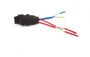

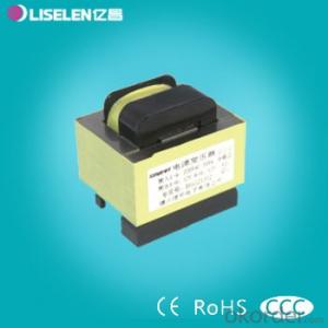
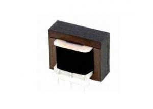
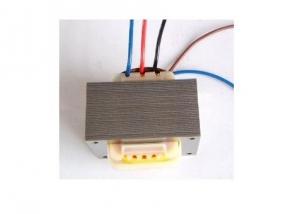
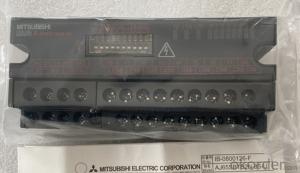
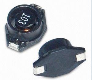
Low Frequency Electronic Transformer
- Ref Price:
-

- Loading Port:
- China Main Port
- Payment Terms:
- TT or LC
- Min Order Qty:
- 800 Pieces pc
- Supply Capability:
- 10000 Pieces per Month pc/month
OKorder Service Pledge
OKorder Financial Service
You Might Also Like


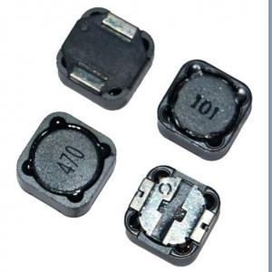
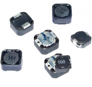
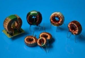
*Electric power Inductor
*High power storage
*Easy insertion,low price
*Used in various electronic and industry products
Our products have gained the international certifications, such as CQC, CE, RoHS, UL and so on, from internationally powerful authorities. We have got ISO9001 certificate. We promise to offer the best products to our clients.We look forward to cooperating with all friends for more mutual benefits. |
- Q: For example, if you put 10 amps through an inductor using 10 volts, is the field any stronger than a field produced by 10 amps going through the same inductor at 1 volt? I've been told that the only factors that effect the strength of an electromagnet are the physical specs, i.e. turns, core, guage, etc., and one electrical factor, current. I know that can't be true, because my house's water pump is able to substitute current for voltage in order to create the same output.More specifically, it runs on either 5A x 230V, or 10A x 115v. Which means that voltage must play a factor in the strength of the magnetic fields created by it's armatures. I theorized that the current going through an inductor is what determines the size, or far-reachingness of the field, while the voltage is what backs up the magnetic field, or gives it it's rigidity. So what's the answer??
- The variable that you haven't mentioned is the resistance of the inductor. At steady-state (DC), the voltage needed will be the current multiplied by the resistance. The equations for magnetic field rely only on current for simple structures, and voltage enters the picture through the resistance for DC circuits. In an AC circuit (which is what your water pump is), the current is usually established by the inductance and the amplitude and frequency of the voltage source. The resistance usually represents an undesired loss, but it will affect the current amplitude. In your water pump, you are trying to deliver mechanical power to a load (the water pressure), and this is represented as a resistance in the motor equivalent circuit. But instead of being a loss, the resistance models the delivery of power to a mechanical load. An unloaded motor draws relatively little current compared to full load, and the current that it does draw is out-of-phase with the applied voltage, which results in little real power actually consumed. Under no-load conditions, most of the power consumed is caused by the line current flowing in the winding resistance. As the mechanical load on the motor is increased, the line current increases, and becomes more in-phase, resulting in significant power consumption, although most of the power is not consumed in the motor, but actually delivered to the load. Your water pump has two sets of windings, and these are either wired in series, or parallel to determine the voltage and current needed. The magnetic field is established by the number of turns of a coil, multiplied by the current in the coil. The power rating of the motor is the constant, so at 230V, the current drawn would be half of that drawn at 115V. So at 230V, the number of turns in the coil is doubled, and the current is halved, resulting in exactly the same peak magnetic field amplitude as the 115V case.
- Q: I plan on making a 500mH inductor, but I'm not sure how big it needs to be to allow the space for the number of turns it needs with a reasonable size wire. (Reasonable size meaning it is readily available and not so small soldering burns through the wire.)
- 500mh Inductor
- Q: I can't find ferrite beads in the local market, can I disassemble normal ferrite inductors (coils) and use their cores as ferrite beads ?
- It's possible, but the inductance of the bead will be small compared to a typical core inductor. Use a very small core.
- Q: An Lc Circuit has an inductance of L 0.020 H and a capacitance C 12 microfarads. The total energy stored in the circuit is E 1.0 Joule.a) what is the maximum magnitude current across the inductor?b) What is the maximum magnitude voltage across the capacitor? c) What is the time interval between the occurrence of maximum magnitude current and maximum magnitude capacitor voltage?Any help would be appreciated. I have an answer for part a and b, however I would like to check that answer and am unsure as to how to solve part c. Thanks!
- The energy move back and forth between the inductor and capacitor. Each component will store all of the energy of an instant. You can figure out Imax and Vmax by using E.5L I^2 or .5 C V^2 and letting E1 J. Just for clairification Imax and Emax are 180 degees out of phase. The angular frequency is w1/sqrt(L C). The period is 2 pi/w.
- Q: Find the equivalent inductance for each of the series and parallel combinations
- It's the same as parallel and series resistors. 1) has 2H in series with 2H, making 4H, in parallel with 12, making 3, which is in series with 2, making 5 total. 2) Re the wire, it shorts out the 6H and the 3H inductors, so that leg just has 18H. Other leg has 10 and 15 in parallel, equivalent to 6H. In series with 3, that makes 9H. so you have 9 in parallel with 18, and that combo in series with 1 .
- Q: i'm an older brother who just wants to build his little brother a fairly decent sound system for his car (he just got his licence and dad bought him a second hand car). odd thing is, my bro likes it more if i build him stuff rather than buy them for him. now, i've seen all the formulas, guides, calculations, ohms, farads and self help guides but I cant make heads or tails about it considering i'm an architecture student and numbers and crud like that confuse me to no end. i'm pretty good when it comes to building the enclosures but i'm crap at the electronics stuff. i've already got a set of subs that dad bought (200 watts each) and another set that a cousin gave me (50 watts each) and they're all 10 inches wide. can anyone help me? what kind of inductors and capacitors do need to for both the 200 watts set and the 50?
- Boss CAP10 10 Farad Capacitor was super easy to install. Comes with all the stuff you need. Is really cool when it's lit up and and the digital gauge is pretty neat to. Charging it before installing was really easy too. Just follow the directions. Completely stopped my headlights and gauges from dimming and my subs and all around stereo is much cleaner and crisp. Awesome product at a great price. Just purchase the right size for the amp that you have. Another post and a little research showed me that for every 500 watts you need 1 farad in capacitance. You can't have too much capacitance so being that my amp is a 2000 watt amp I bought the 10 farad, Good luck with whatever product you purchase but I have had good success with this one and believe it's well worth the money.
- Q: A 1E-6 F capacitor has a charge of 10.0 microC. It is connected to a 1.0 H inductor at t 0. What is the potential energy of the capacitor and the potential energy of the inductor at t 1 second?
- The angular velocity (omega) here sqrt(1/LC) sqrt(1/(1x10^-6*1) 1000 rad/s Q0 10^x10^-6C Now the charge on a capacitor in an LC oscillator q Q0*cos(omega*t) 10.x10^-6*cos(1000*1) 5.62x10^-6C So the energy q^2/2C (5.62x10^-6)^2/(2*1x10^-6) 1.58x10^-5J Now the current i -omega*Q0*sin(omega*t) -1000*10x10^-6*sin(1000) -0.00827A Energy in an inductor 1/2*l*i^2 1/2*1.0*(0.00827)^2 3.42x10^-5J
- Q: A 2.50mH inductor is connected in series with a dc battery of negligible internal resistance, a 0.760kOhm resistor, and an open switch.How long after the switch is closed will it take for the current in the circuit to reach half of its maximum value ?How long after the switch is closed will it take for the energy stored in the inductor to reach half of its maximum value?
- L 2.5*10^-3 H R 760 Ω This will produce a very short time constant T L / R 3.2895 * 10^-6 s The current is i Imax * (1 - e^(-t/T)) When i 0.5*Imax 0.5 1 - e^(-t/T) e^(-t/T) 1 - 0.5 0.5 -t / T ln(0.5) -0.69315 t --0.69315 * 3.2895*10^-6 s 2.28*10^-6 s 2.28 μs Emax 0.5*L*Imax^2 When E 0.5*Emax i^2 / Imax^2 0.5 so i Imax / sqrt(2) 0.7071*Imax 0.7071 1 - e^(-t/T) e^(-t/T) 1 - 0.7071 0.2929 -t / T ln(0.2929) -1.228 t --1.228 * 3.2895*10^-6 s 4.04*10^-6 s 4.04 μs
- Q: A 4-mH inductor is connected to an ac voltage source of 151.0 V rms. If the rms circuit is .820 A, what is the frequency of the source?This is NON-Calculus based Physics! Please Help! Thx!
- I V/XL XL V/I 151/0.820 184Ω Now XL 2π*f*L f XL/(2π*L) 184/(2π*4x10^-3) 7330Hz
- Q: I know the resonant frequency is 1/sqrt(LC) and quality factor (1/r)(sqrt(L/C)) and I can use these to calculate my component values with a given resonant frequency, but every inductor has a resistance. How do I account for that in my design?Thank you in advance!
- Just insert a series resistor that is equal to the ESR of the inductor. If fr is large, you may also want to include the ESR of the cap.
1. Manufacturer Overview
| Location | Shenzhen, Guangdong, China (Mainland) |
| Year Established | 2006 |
| Annual Output Value | US$2.5 Million - US$5 Million |
| Main Markets | North America; South America; Eastern Europe; Southeast Asia; Africa; Oceania; Mid East; Eastern Asia; Western Europe; Central America; Northern Europe; Southern Europe; South Asia; Domestic Market |
| Company Certifications | CE Certificates |
2. Manufacturer Certificates
| a) Certification Name | |
| Range | |
| Reference | |
| Validity Period |
3. Manufacturer Capability
| a) Trade Capacity | |
| Nearest Port | Shekou,Yantian |
| Export Percentage | 51% - 60% |
| No.of Employees in Trade Department | 3-5 People |
| Language Spoken: | English, Chinese |
| b) Factory Information | |
| Factory Size: | 3,000-5,000 square meters |
| No. of Production Lines | 9 |
| Contract Manufacturing | OEM Service Offered Design Service Offered Buyer Label Offered |
| Product Price Range | Average |
Send your message to us
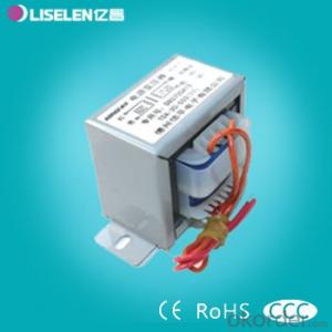
Low Frequency Electronic Transformer
- Ref Price:
-
- Loading Port:
- China Main Port
- Payment Terms:
- TT or LC
- Min Order Qty:
- 800 Pieces pc
- Supply Capability:
- 10000 Pieces per Month pc/month
OKorder Service Pledge
OKorder Financial Service
Similar products
Hot products
Hot Searches
Related keywords

