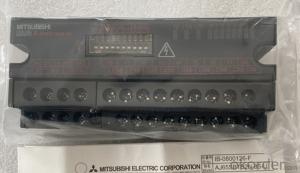


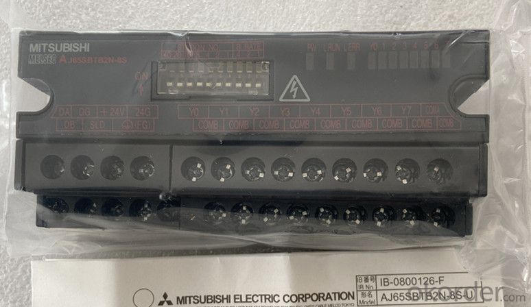


Organic Materials DC Motor Newest Mitsubishi Melsec AJ65SBTB2N-8S
- Ref Price:
-

- Loading Port:
- Shanghai
- Payment Terms:
- TT OR LC
- Min Order Qty:
- 1 kg
- Supply Capability:
- 2000 kg/month
OKorder Service Pledge
OKorder Financial Service
You Might Also Like


Specification
A small remote I / O module used as a remote I / O station for control and
communication links (hereinafter referred to as "CC link"). Its features are as
follows:
(1) The small remote I / O module reduces the volume while maintaining all the
functions of the traditional module.
(2) More models of small remote I / O module series
Waterproof terminals are added to the small remote I / O module series for CC
link system. Along with the traditional terminal block type, there are also
quick connector type modules and FCN connectors
Type and connector type, now there are five models of products.
In addition to the traditional 16 point and 32 point remote I / O modules, an
8-point type is added, so that users can choose the most appropriate module
according to their own purpose and environment.
(3) The 4-wire small remote I / O module is easy to connect to the 4-wire
sensor.
It can be easily connected to the 4-wire sensor through the common pin provided
on each plug. It is not necessary to install relay terminal block.
For 4-wire small remote I / O modules, one sensor is connected to one plug.
Therefore, the sensor can be changed through the plug, reducing the operation
steps.
(4) The terminal block connection makes it easy to connect 2-wire and 3-wire
sensors or loads.
Because the terminal block connection allows the connection of 2-wire and 3-
wire sensors or loads, there is no need for a common connector, which makes the
connection easier.
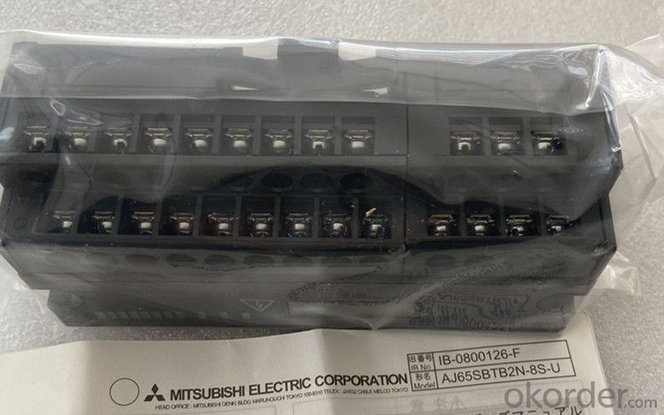
(5) Minimize wiring
(a) Terminal block module
By using the self tightening screw on the terminal block, the wiring steps can
be significantly reduced.
(b) Quick connector module, connector module
The wiring steps can be significantly reduced by using the parallel wire
pressure wiring method (without welding, stripping the shielding layer and
screwing).
(c) FCN connector type module
Wiring steps can be significantly reduced by using 40 pin connectors for I / O
parts.
(6) Waterproof remote I / O module has improved waterproof and oil proof effect
The waterproof remote I / O module adopts a protective structure compatible
with IP67, which can be used more safely in the presence of water and oil.
(7) Up to 64 remote I / O modules can be connected
In CC link system, each master station can connect up to 64 remote I / O modul
Since each remote I / O module accounts for 32 points, a maximum of 2048 link
points can be set.
(8) The module can be replaced without stopping the CC link system
The dual block terminal block used for CC link cable connection can be used to
replace the module without stopping the operation of CC link system.
(9) It can be installed directly on the machine
The terminal block type remote I / O module can be installed directly on the
machine because there is a live area protected by a finger guard in the area
above the terminal block.
(10) The module can be installed in 6 directions
Small remote I / O modules can be installed in 6 different directions. (there
are no restrictions on the installation direction.)
The module can also be installed with DIN rail.
(11) Transistor output module with improved protection function
Transistor output module in order to achieve better module protection ability,
as a standard model, its design adopts short-circuit protection, overload
protection, overheating protection and overvoltage protection.
Therefore, the reliability of PLC system has been further improved.
- Q: An inductor has an impedance of 30.0 Ω and a resistance of 20.0 Ω at a frequency of 80.0 Hz. What is the inductance? (Model the inductor as an ideal inductor in series with a resistor.)?
- Impedance for an ideal inductor is: Z j*omega*L For a real inductor with a parasitic resistance modeled in series: Z R + j*omega*L j refers to the imaginary number unit. omega is the angular frequency of the signal. We were given the cycle frequency and we can convert: omgea 2*Pi*f I assume your 30 ohms refers to the magnitude of impedance. Combine both components of the complex number using the Pythagorean theorem. Zmag sqrt(R^2 + (omega*L)^2) And with a substitution: Zmag sqrt(R^2 + (2*Pi*f*L)^2) Square both sides: Zmag^2 R^2 + (2*Pi*f*L)^2 Solve for L: (2*Pi*f*L)^2 Zmag^2 - R^2 2*Pi*f*L sqrt(Zmag^2 - R^2) Resulting expression: L sqrt(Zmag^2 - R^2)/(2*Pi*f) Data: Zmag:30.0 Ohms; R:20.0 Ohms; f:80.0 Hz; Result: L 0.04449 Henries Or, with a convenient prefix: L 44.49 milliHenries
- Q: Current through an inductor is turned on at time t0, as shown in the figure. Vscos(200*pi*t). Calculate the energy delivered to the inductor at t21 ms.Here's the figure:
- I(1/L)*integral(V dt). Note that you need to consider the initial conditions, when finding the solution. Once you get the solution, just plutg in t21ms.
- Q: Does the voltage in the circuit start at applied voltage with no current then voltage drops and current increases? Is this because there is a voltage drop across the coil and its magnetic field?
- in a inductor free electrones r pesent when current is passed through it the free electrones start moving in a definite direction,this causes magnetism.
- Q: here's the text which contains it,Referring to figure, it can be seen that no power is disspated in a pure inductor. In the first quarter of cycle, both V and I are positive so the power is positive, which means that energy is supplied to the inductor. In the second quarter, V is positive but I is negative. Now power is negative which implies that the energy is returned by the inductor(The figure looks something like this) ::
- Yes, you're correct. Your picture shows the correct phase relationship between voltage and current in an inductor, and in that case your description is correct.
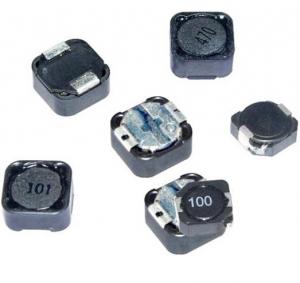
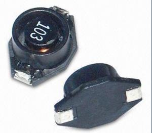
- Q: Hello everyone, Anyone knows how to findout the rating of 3R3 inductor which is broken and needed to be replaced for a tablet xtouch X906? Please help.Thank youBernard
- 3R3 is typically a 3.3 mH but could be a 3.3 uH depending on the case size. Most are surface mount and if you can match it pictorially on digikey, you might have a chance in getting the same part. It is always best to have the manufacturer replace the part as they can test other areas that may be broken and need repair. Also you can do more damage if the proper part is not installed properly or if you overheat sensitive parts.
- Q: How do you add inductors?
- it depends . inductors in series add directly so 1 mH + 1 mH in series is equivalent to a single 2 mH inductor Lt total inducatance Ln n'th inductor Lt L1 + L2 + L3 + . + Ln inductors in parallel add inversely 1 mH + 1 mH in parallel 1/L 1/1 + 1/1 Lt total inducatance Ln n'th inductor 1/Lt 1/L1 +1/L2 + +1/Ln
- Q: An inductor of 170 turns has a radius of 8 cm and a length or 30 cm. The permeability of free space is 1.25664 x 10^-6 N/A^2.Find the energy stored in it when the current is 0.6 A.
- Inductance of a solenoid, air L ??N?A/Ln Ln is length in meters A is area in meters? N is number of turns ?? is the magnetic constant 1.2566×10?6?H/m (or T·m/A) use the above formula to calculate inductance. Change units to meters. then use E ?LI? Energy in an inductor to get the energy. .
- Q: and what do you think its should resistance be
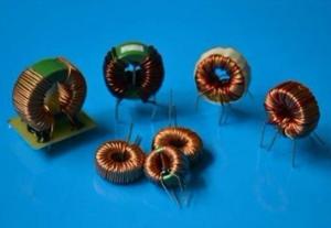
- An inductor is a hypothetical two terminal circuit element which produces a voltage across its terminals which is proportional to the rate of change of current through it. V L*di/dt the constant of proportionality L is called inductance. It is measured in henrys if the voltage is in volts and the current in amps. Usually we realise an inductor with a coil of wire. energy is stored in the magnetic field produced, which gives us this current/voltage relationship. But there are also other circuits which can have this behaviour: these are often very useful becuase inductors made with coils are usually large and heavy. Inductance circuits can be made with amplifiers and capacitors and resistors, so are much better. An ideal inductor has no resistance. An inductor made from a coil will have some resistance, unless it is made from a superconducting material! An inductor made from amplifier circuits and RC networks can sometimes have much better characteristics (more linear and much lower resistance) than an inductor made from a coil.
- Q: A circuit consists of a 17 ? resistor and a 510 mH inductor connected in series to a 16 V battery. What is the value of the current when the current is increasing at the rate of 8 A/s?Answer in units of A.
- hyperphysics.phy-astr.gsu.edu/hba the equation for I is given. dI / dt V/L e^(-tR/L) calculate dI / dt 8, you will find a value for t, plug is value for t into the equation for I
- Q: Help out a brother here.The graph below shows the voltage across a 560 mH inductor vs. time
- Since the plot can be separated into piecewise functions, the easiest way is to integrate the functions at the points you need Remember the current across an inductor cannot change instantaneously First off: Voltage across an inductor V L di/dt Rearranging for current i 1/L * [integral from t0 to t chosen] v(t) dt from t0 to t7*10^-6, solving the integral 1/560*10^-3 * [-400t] from t0 to t7 [-400*7*10^-6]/0.56 -5mA Similarly, repeat from t7us to t9us and sum the answers from t7*10^-6 to t9*10^-6, solving the integral 1/560*10^-3 * [320t] from t7*10^-6 to t9*10^-6 [320*9*10^-6 - 320*7*10^-6] / 0.56 1.14 mA Answer: Current at 9us -5mA + 1.14 mA -3.86mA
Send your message to us
Organic Materials DC Motor Newest Mitsubishi Melsec AJ65SBTB2N-8S
- Ref Price:
-
- Loading Port:
- Shanghai
- Payment Terms:
- TT OR LC
- Min Order Qty:
- 1 kg
- Supply Capability:
- 2000 kg/month
OKorder Service Pledge
OKorder Financial Service
Similar products
Hot products

Hot Searches

