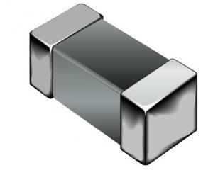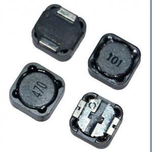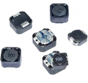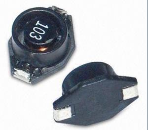
PBP Series Shielded SMD Power Inductor
- Ref Price:
-

- Loading Port:
- China Main Port
- Payment Terms:
- TT or LC
- Min Order Qty:
- 1000 Pieces pc
- Supply Capability:
- 20,000 Pieces per Day pc/month
OKorder Service Pledge
Quality Product, Order Online Tracking, Timely Delivery
OKorder Financial Service
Credit Rating, Credit Services, Credit Purchasing
You Might Also Like
1. pbp series shielded smd power Inductor
2. Rated current:0.5-10A
3. Inductance0.5~6000uH
4. Quality assured
5. competitive price
smallest possible size and high performance they are with high energy storage
Feartures:
The Surface Mount Inductors are designed for the smallest possible size and high performance,
They are with high energy storage and very low resistance making them the ideal inductors for
DC-DC conversion in the following application.
- Q:A 90 mH inductor, a 60 uF Capacitor, a 6 Ohm resistor and a 60 uF Capacitor are connected in series and supplied via a 70 Hz voltage source:Vs(t) 141.4213*sin(wt+70°) V.Determine the total impedance of the circuit and express your answer in polar form: /_ ° Ohms.The output of the circuit is the voltage across the inductor. Determine the output voltage and express your answer in polar form: /_ ° VCalculate the output voltage in rectangular form: j V
- 60uf Capacitor
- Q:An inductor of 170 turns has a radius of 8 cm and a length or 30 cm. The permeability of free space is 1.25664 x 10^-6 N/A^2.Find the energy stored in it when the current is 0.6 A.
- Inductance of a solenoid, air L ??N?A/Ln Ln is length in meters A is area in meters? N is number of turns ?? is the magnetic constant 1.2566×10?6?H/m (or T·m/A) use the above formula to calculate inductance. Change units to meters. then use E ?LI? Energy in an inductor to get the energy. .
- Q:how do u calculate the SRF of a inductor,for example i have a 90Mhz oscillator,but i need a RF choke to block the RF from entering the other part of the circuit,so the SRF of the RF choke should be more than 90Mhz may be 110Mhz.,so how can i calculate the SRF,i make inductors by myself.so please help me out.
- I was in The Corps right as Vietnam was ending and the rule against laying hands on recruits was not yet in place. It is nothing like it was but I've heard from some more recent marines that things still happen but nothing like it used to be. I saw a guy get spin kicked when standing at attention in the barracks by a DI who was some kind of a kung fu badass and saw a number of recruits get punched. I personally got punched in the gut pretty hard. I also saw a guy get led around by a string tied around his dick on the parade field with his pants around his ankles for screwing up a marching formation. FYI my platoon also had a guy jump from our 3rd story barracks down to the hard deckwe never heard if he lived or died, nothing was ever told to us and the DI's just went ahead with training like nothing had happened. Parris Island was not for the faint of heart back then.
- Q:a) much energy is stored in a 10.2 mH inductor carrying a 1.15 A current?b) How much current would the inductor mentioned in part A have to carry to store 1.00 J of energy?c) Is the amount of current found in part B reasonable for ordinary laboratory circuit elements?-Yes, it's reasonable for ordinary laboratory circuit elements.-No, it's not reasonable for ordinary laboratory circuit elements. It's too large.
- a) The energy stored in an inductor is given by U 1/2 L I^2 1/2*(10.2E-3)*(1.15)^2 6.74E-3J 6.74 mJ b) The current required to have 1 J stored in the inductor is then I sqrt (2*U/L) sqrt(2*1/10.2E-3) 14. A That is not an unreasonable amount of current. The inductor needs to be made of wire with diameter larger than a 30 AWG otherwise it will melt. Not sure if a 10.2mH inductor can be made with such wire.
- Q:An inductor (L 400 mH), a capacitor (C 4.43 ?F), and a resistor (R 500 ) are connected in series. A 48.0 Hz AC generator connected in series to these elements produces a maximum current of 290 mA in the circuit. What is the required maximum voltage?
- circuit impedance Z R + j w L - j / (w C) where w is the angular frequency (rads/sec). The voltage is then given by V Z I (R + j w L - j / (w C)) I I assume that what you are given is the maximum amplitude of the current and what you want is the resulting voltage amplitude of the entire circuit. That is |V| |(R + j w L - j / (w C))| I So, just find the amplitude of the impedance and multiplied by the given current and you are done.
- Q:Current through an inductor is turned on at time t0, as shown in the figure. Vscos(200*pi*t). Calculate the energy delivered to the inductor at t21
- Since V L(di/dt) I (1/L)(∫(VI)dt) I (1/0.038)(1/200π)(sin (200πt)) 1/(7.6π)(sin (200πt)) and E ∫(VI)dt E (1/2)L(I?) 200πt f 100 Hz, T 10 milliseconds, 21 milliseconds 720° +36° at 21 milliseconds, sin (200πt)) sin 36° 0.588 I 0.588/(7.6π) 0.0246 amps E (1/2)(0.038)(0.0246^2) 11.5 u joules
- Q:current under one volt?
- Variable inductors are not used very often, but a powdered iron toroid could be used. I would be built something like an auto transformer. Most diodes have less than a volt when forward biased.
- Q::)please be as explicit as possible.Thanks!
- I guess a coupled inductor would be where two separate inductors are mounted near each other so that they couple. It can't be called a transformer because there isn't a single device. I have never seen this used deliberately, but it could be a handy trick if you need an adjustable coupling by bending one of the inductors. Best of luck getting it past AutoCad. The difference from a transformer is that a transformer is a single device with two or more windings. I think a coupled inductor is two or more separate windings that are mounted near each other.
- Q:A circuit consists of a 17 ? resistor and a 510 mH inductor connected in series to a 16 V battery. What is the value of the current when the current is increasing at the rate of 8 A/s?Answer in units of A.
- hyperphysics.phy-astr.gsu.edu/hba the equation for I is given. dI / dt V/L e^(-tR/L) calculate dI / dt 8, you will find a value for t, plug is value for t into the equation for I
- Q:A 24.0 V battery is in series with a switch, a 0.40 H inductor, time constant of 16 ms, and a 25 ohm resistor.(a) Find the potential differences across the inductor at t τ. V(1L) (b) Find the potential differences across the resistor at t τ. V(1R) (c) Find the potential differences across the inductor at t 3τ. V(2L) (d) Find the potential differences across the resistor at t 3τ. V(2R) Me and my partner are completely stuck on here, if someone could help i would be incredibly greatful!
- The time constant of an inductor is L/r where the inductor is modelled by an ideal inductor L and a resistor r in series. So your inductor can be represented as 0.4H in series with a resistance of 0.6/(16*10^-3) 37.5 Ohms. the total resistance in the circuit is R 37.5 + 25 62.5 ohms, and the overall time constant is 0.4/62.5 6.4ms Now you can use the formula I V/R(1 - e^(-t/6.4*10^-3)) where V 24 to calculate the current at any time t. I am not certain what the symbol τ means in your question, so I am going to leave it to you to calculate the value of I at τ and 3τ (Iτ I3τ) Once you have these currents you can answer the questions as follow - b) with Iτ use V IR to find the voltage across the 25ohm resistor a) subtract the answer to (b) from 24v then do the same with I3τ
Our products have highest quality and competitive prices.Our well-equipped facilities and excellent quality control throughout all stages of production enable us to guarantee total customer satisfaction. As a result of our high quality products and outstanding customer service, we have gained a global sales network.
1. Manufacturer Overview |
|
|---|---|
| Location | Guangdong,China (Mainland) |
| Year Established | 2010 |
| Annual Output Value | US$10 Million - US$50 Million |
| Main Markets | North America; South America; Eastern Europe; Southeast Asia; Africa; Oceania; Mid East; Eastern Asia; Western Europe |
| Company Certifications | ISO 9001:2000 |
2. Manufacturer Certificates |
|
|---|---|
| a) Certification Name | |
| Range | |
| Reference | |
| Validity Period | |
3. Manufacturer Capability |
|
|---|---|
| a)Trade Capacity | |
| Nearest Port | |
| Export Percentage | 41% - 50% |
| No.of Employees in Trade Department | |
| Language Spoken: | |
| b)Factory Information | |
| Factory Size: | |
| No. of Production Lines | |
| Contract Manufacturing | OEM Service Offered Design Service Offered Buyer Label Offered |
| Product Price Range | |
Send your message to us
PBP Series Shielded SMD Power Inductor
- Ref Price:
-
- Loading Port:
- China Main Port
- Payment Terms:
- TT or LC
- Min Order Qty:
- 1000 Pieces pc
- Supply Capability:
- 20,000 Pieces per Day pc/month
OKorder Service Pledge
Quality Product, Order Online Tracking, Timely Delivery
OKorder Financial Service
Credit Rating, Credit Services, Credit Purchasing
Similar products


New products


Hot products