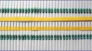

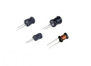
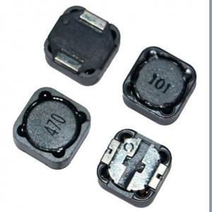
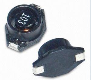
Color Loop Inductor
- Ref Price:
-

- Loading Port:
- China Main Port
- Payment Terms:
- TT or LC
- Min Order Qty:
- 1000 Pieces pc
- Supply Capability:
- 10000 Pieces per Week pc/month
OKorder Service Pledge
OKorder Financial Service
You Might Also Like


1.Qualified material competative price
2.small loss
3.usage:instrutment phase:single
4.coil structure:axial
5.core dimension:adjustable by clients
6.size:follow according client's requirement
7.Remark:we can produce it according client's requirement
Our products have gained the international certifications, such as CQC, CE, RoHS, UL and so on, from internationally powerful authorities. We have got ISO9001 certificate. We promise to offer the best products to our clients. We look forward to cooperating with all friends for more mutual benefits.
- Q: For example, if you put 10 amps through an inductor using 10 volts, is the field any stronger than a field produced by 10 amps going through the same inductor at 1 volt? I've been told that the only factors that effect the strength of an electromagnet are the physical specs, i.e. turns, core, guage, etc., and one electrical factor, current. I know that can't be true, because my house's water pump is able to substitute current for voltage in order to create the same output.More specifically, it runs on either 5A x 230V, or 10A x 115v. Which means that voltage must play a factor in the strength of the magnetic fields created by it's armatures. I theorized that the current going through an inductor is what determines the size, or far-reachingness of the field, while the voltage is what backs up the magnetic field, or gives it it's rigidity. So what's the answer??
- The variable that you haven't mentioned is the resistance of the inductor. At steady-state (DC), the voltage needed will be the current multiplied by the resistance. The equations for magnetic field rely only on current for simple structures, and voltage enters the picture through the resistance for DC circuits. In an AC circuit (which is what your water pump is), the current is usually established by the inductance and the amplitude and frequency of the voltage source. The resistance usually represents an undesired loss, but it will affect the current amplitude. In your water pump, you are trying to deliver mechanical power to a load (the water pressure), and this is represented as a resistance in the motor equivalent circuit. But instead of being a loss, the resistance models the delivery of power to a mechanical load. An unloaded motor draws relatively little current compared to full load, and the current that it does draw is out-of-phase with the applied voltage, which results in little real power actually consumed. Under no-load conditions, most of the power consumed is caused by the line current flowing in the winding resistance. As the mechanical load on the motor is increased, the line current increases, and becomes more in-phase, resulting in significant power consumption, although most of the power is not consumed in the motor, but actually delivered to the load. Your water pump has two sets of windings, and these are either wired in series, or parallel to determine the voltage and current needed. The magnetic field is established by the number of turns of a coil, multiplied by the current in the coil. The power rating of the motor is the constant, so at 230V, the current drawn would be half of that drawn at 115V. So at 230V, the number of turns in the coil is doubled, and the current is halved, resulting in exactly the same peak magnetic field amplitude as the 115V case.
- Q: A 24 mH inductor is connected to a outlet where the rms voltage is 123 V and thefrequency is 60 Hz.Determine the energy stored in the inductorat t 5.2 ms, assuming that this energy iszero at t 0.Answer in units of J.Please help!!!
- Energy stored in the inductor 1/2 L * I^2
- Q: does the air inductor in my 2001 venture need to be cleaned or replaced?.thanx.
- the air inductor, that little plastic thing that hooks up to your fuel system? If it is cheap, I'd say replace it. What does the air inductor do anyway? You don't give a lot of information here. is your motorcycle dying on you when you give it the gas? (grin). Will it start at all? What are the symptoms? Thanks! kdp
- Q: Hi, can somebody please help me with this inductor problem? I'm stuck on it and need some help i think that I have the general idea, but need some guidance.
- Hello my old friend, I see you're still trying to penetrate basic electrical theory. Let's see if you're correct here: The relevant equation (the origin of which you can check in any circuitry textbook) is; v(t) L.di/dt where v is the voltage applied to the inductor. Therefore; i (1/L).∫v.dt 500 ? ∫v.dt when v is constant this gives i 500 ? v ? t Because of the step-wise shape of your voltage curve, we have to determine the integral in time-steps: From t 0 to 5μs, i 500 ? 10 ? t so it is the line i 5000 ? t, reaching 25mA after 5μs. From t 5 to 15μs, i drops with a gradient of -5000 from its value of 25mA. In this range it is therefore given by the straight line i 0.05 – 5000 ? t. and it reaches a value of -25mA at t 15μs. From t 15 to 20μs the gradient is again +5000 so that the current is given by the equation: i -0.1 + 5000t so that it rises to a value of zero at t 20μs. This is to be expected since the total postive area (integral) under the voltage curve equals the total negative area, so that the overall integral from 0 to 20μs is zero. In conclusion, I don't know whether you're right or wrong because I don't quite follow your thinking. Anyway the above is how it is! I'm afraid I can't get a sketch into Y!A. I hope you're into BA awards in the meantime! Edit: I'm afraid Steven (notwithstanding his HUGE experience) gets it wrong. For example in the second interval 5 to 15μs he calculates the correct change in current but fails to account for the 25mA flowing at the start of that interval. In the third interval he makes (in principle) the same mistake. He also fails to provide any clue about the current waveform as requested in the question!
- Q: here's the text which contains it,Referring to figure, it can be seen that no power is disspated in a pure inductor. In the first quarter of cycle, both V and I are positive so the power is positive, which means that energy is supplied to the inductor. In the second quarter, V is positive but I is negative. Now power is negative which implies that the energy is returned by the inductor(The figure looks something like this) ::
- Yes, you're correct. Your picture shows the correct phase relationship between voltage and current in an inductor, and in that case your description is correct.
- Q: how to relate the amount of turns for inductor of crystal radio to its performance?
- They can be overlapping if you do not use the traditional slider on the coil to tune stations. The slider needs to be able to adjust the length of the coil to change frequency and if the coils are overlapping you would limit its range of tuning. In some crystal radio configurations a variable capacitor is used for selecting the frequency and these usually have overlapping windings. Most crystal radio enthusiasts agree that the sensitivity and selectivity is better with a single wound air core coil.
- Q: A 215 ? resistor and a 0.2 H inductor are connected in series with an AC source of 234 V and frequency 106 Hz. (a) What is the current in the circuit? (b) Calculate the phase angle between the current and the voltage of the AC source. I have tried every way possible to find the correct answer, which is a) 0.925A and b) 31.8 degrees, couldn't figure it out. Your help will be greatly appreciated. Thank you!
- The voltage around the inductor is 114.5 V rms and L 0.seventy six Henry commencing with this equation: one hundred twenty iR + j(XL)i one hundred twenty (ninety)i + jwLi the place w 2?f 377 for f 60 Hertz The impedance Z R + j377L ninety +j377L The resistor R and the XL of the inductor are at marvelous angles to a minimum of one yet another V inductor ?((one hundred twenty? - Vr?) ?((one hundred twenty? - 36?) 114.5 V rms XL (114.5/36)ninety 286 ohms yet XL 377L so 377L 286 L 0.seventy six Henry
- Q: Assume that we set up a circuit with a resistor, a capacitor and an inductor all in serial. In which condition is the magnitude of the current is maximum over the resistor?
- The current is a maximum at resonance, when the reactances of the cap and the inductor cancel out. But the current will not exceed the value you would get with the resistor alone. resonance frequency: f 1/(2π√(LC)) .
- Q: A constant voltage of 5.00 V has been observed over a certain time interval across a 1.10 H inductor. The current through the inductor, measured as 2.00 A at the beginning of the time interval, was observed to increase at a constant rate to a value of 6.00 A at the end of the time interval. How long was this time interval?
- Jag tycker det ?r lustigt hur du ska ?vers?tta detta f?r att se vad jag skrev. L?ser du fortfarande h?r? Du borde sluta nu.
- Q: An inductor is connected to an AC generator.As the generator's frequency is increased, what happens to the current in the inductor?The current increases.The current decreases.The current does not change.Don't just choose one, explain why you choose it.
- The current decreases the current in the inductor : I V/XL ----I ∝ 1/XL XL 2πf* L ---XL ∝ f If f is increased ---XL is increased ---the current will be decreased
1. Manufacturer Overview
| Location | Shenzhen, Guangdong, China (Mainland) |
| Year Established | 2006 |
| Annual Output Value | US$2.5 Million - US$5 Million |
| Main Markets | North America; South America; Eastern Europe; Southeast Asia; Africa; Oceania; Mid East; Eastern Asia; Western Europe; Central America; Northern Europe; Southern Europe; South Asia; Domestic Market |
| Company Certifications | CE Certificates |
2. Manufacturer Certificates
| a) Certification Name | |
| Range | |
| Reference | |
| Validity Period |
3. Manufacturer Capability
| a) Trade Capacity | |
| Nearest Port | Shekou,Yantian |
| Export Percentage | 51% - 60% |
| No.of Employees in Trade Department | 3-5 People |
| Language Spoken: | English, Chinese |
| b) Factory Information | |
| Factory Size: | 3,000-5,000 square meters |
| No. of Production Lines | 9 |
| Contract Manufacturing | OEM Service Offered Design Service Offered Buyer Label Offered |
| Product Price Range | Average |
Send your message to us
Color Loop Inductor
- Ref Price:
-
- Loading Port:
- China Main Port
- Payment Terms:
- TT or LC
- Min Order Qty:
- 1000 Pieces pc
- Supply Capability:
- 10000 Pieces per Week pc/month
OKorder Service Pledge
OKorder Financial Service
Similar products

Hot products

Hot Searches

