


Three Phase Three Wire Type Mitsubishi Driver QH42P With Intelligent
- Ref Price:
-

- Loading Port:
- China main port
- Payment Terms:
- TT OR LC
- Min Order Qty:
- 1 kg
- Supply Capability:
- 2300 kg/month
OKorder Service Pledge
OKorder Financial Service
You Might Also Like


Specification
Three phase three wire type.
Number of measuring circuits: 1 circuit.
Measurement items: power consumption (consumption and regeneration), current,
voltage, power, power factor, etc. it is a product group of elevtric energy
measurement modules that can simply measure a variety of energy information.
With only one module, you can measure various detailed information related to
power (consumption and regeneration), reactive power, current, voltage, power,
power factor and frequency. Mitsubishi 1 / O module user manual.
The minimum and maximum values can be continuously monitored without ladder
program, and two types of upper / lower limit alarm qh42f can be executed. The
power used by the output device can be measured only during the on state.
Therefore, the power during the operation of the equipment and the power in the
beat unit can be obtained. Using 3-phase 3-wire products in one slot can
measure up to 4 circuits, and using 3-phase 4-wire products can measure up to 3
circuits
Therefore, through multi circuit products, electric energy measurement can be
implemented in a small space. Mitsubishi / O module user manual. For example,
one module can be used to measure other loads from the control panel trunk
line.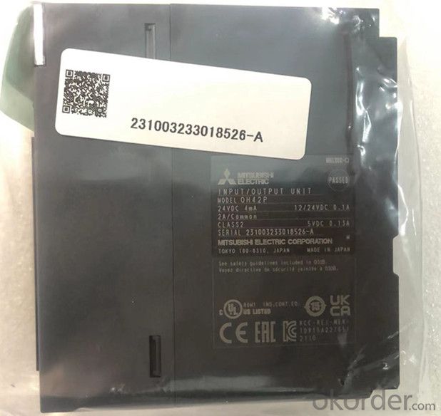
In addition, GX works2 (version 1.90u and higher) can be used to easily set
parameters and bidirectional controllable brick output; 32 o'clock. Rated
current and voltage: AC100 ~ 240V_ 0.6a/1 point, 2.4a/1 public end, 8:1 public
end Mitsubishi / O module user manual. Response time: 1ms + 0.5 cycle.
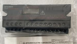
External wiring connection mode: 38 point terminal block (terminal block is
sold separately). Replacement model: ay23, output: 2 channels,
Input (resolution): 0 ~ 4000: - 4000 ~ 4000:0 ~ 12000-12000 ~ 12000: - 16000 ~
16000 output: DC-10 ~ 10V: dc0 ~ 20maqh42p user manual. Conversion speed: 80us
/ 1 channel. 18 point terminal block.
Transformer isolation between power supply and output. High insulation strength
and withstand voltage.
It can isolate electrical interference, such as current and noise. Standard
analog input module. Isolated analog input module. No external isolation
amplifier is required.
When the inter channel isolated analog quantity module is not used.
Qh42p user manual when using inter channel isolated analog module. Expand the
possibility of control with intelligent functions.
Provide various analog modules, which is an ideal choice for process control
applications. It can also meet the needs of high-speed and high-precision
control.
It is most suitable for analog modules in the field of high-speed conversion
control,
Qh42p user manual for a variety of analog-to-digital and digital to analog
conversion module products can be provided
These modules have various functions and achieve maximum flexibility when
connecting devices.
It can meet the needs of high-speed conversion such as frequency converter
control. Various modules with excellent performance
Meet various control requirements from analog quantity to positioning.
Q series module products include a wide variety of / 0, analog and positioning
function modules.
It can fully meet the input and output of switches and sensors, the control of
temperature, weight, flow, motor and driver, and the positioning of high-
precision control in the future! Control requirements in various fields
It can also be combined with CPU module to realize appropriate control. Input
voltage range: AC100-240V. Output voltage: DC5V Output power supply: 2A Ultra
thin power supply. Simplify program debugging
The software component test function with execution conditions can be used to
change the software component value to the user specified value at any step of
the program.
In the past, when debugging a specific circuit program section, it was
necessary to add a program for setting soft components
At present, by using this function, specific loop program segments can perform
actions independently without changing the program. Large, there is no need to
change the program for debugging in the single, the debugging operation is
simple, and the key data is automatically backed up
Automatically save the program and parameter files into the program memory
(flash ROM) without using the backup battery, so as to prevent the program and
parameters from losing the qh42p manual due to forgetting to replace the
battery. In addition, important data such as software component data can be
backed up to standard ROM to avoid planned downtime during long holidays,
These data are lost due to battery depletion. Mitsubishi / / O module user
manual. The next time the power is turned on, the backed up data will be
restored automatically. Through the extension of software components, it is
more convenient to create programs.
The software component can be extended to 60m bits at most
- Q: A real inductor can be modeled as an ideal inductor in series with an internal resistance as illustrated in the figure above.A time-varying current I is passed through a real inductor. At a time when I +4 A and dI/dt +14 A/s, the voltage drop across the inductor is observed to be Va - Vb +185 V. At another time when I +4 A and dI/dt -14 A/s, the observed voltage drop is V'a- V'b +43 V.
- Ldi/dt +4i Vab, L(14) + R(4) 185 L(-14) + R(4) 43 System of linear eqns, add together; 8R 228, R 28.5 ohm
- Q: For the circuit shown in the figure, the switch has been open for a very long time. (a) What is the potential drop across the 15.0-mH inductor just after closing the switch? (b) What is the potential drop across the 70.0-?F capacitor after the switch has been closed for a very long time?
- An inductor is an open circuit at t0 and a short circuit at t∞. A capacitor is a short circuit at t0 and an open circuit at t∞. That makes things very easy. (a) At t0, all you have is a 75? in series with a 25? resistor. So the voltage on the bottom side of the 15mH inductor is +200V????????? +50V. There is no current in the 50? resistor, so no voltage drop, so the other side of the 15mH inductor is at +200V. So the voltage across the inductor is 150V at t0. (b) At t∞, all you have now is a 50? in series with a 25? resistor. So the voltage on the bottom side of the 70μF capacitor (there is no current in the 38? resistor) is +200V????????? +66?V. The voltage on the other side of the 70μF capacitor is +200V. So the voltage across the capacitor is 133? V at t∞.
- Q: A circuit containing a 39-H inductor has an alternating current supplied to it. If is and is find the frequency of the signal.0.033 Hz0.41 Hz0.0052 Hz0.21 Hz
- Look at the question again- you will see it des not make sense. To find the frequency we need to know the series resistance of the inductor, the voltage across the component and the current through it.
- Q: how do u solve for inductor or L if u have a rlc circuit?
- Yo need more info. What else do you know?
- Q: Does current flow through an inductor if it is connected to a dc source without any other component such as resistance or capacitor?
- yes, an inductor presents a very low resistance to DC. An ideal inductor has zero DC resistance, ie, it is a short to a DC source.
- Q: If the current through the inductor drops from 110mA to 50mA in 13useconds? u is micro I think?Any ideas?Thanks
- V L * (di / dt) L 12mH 0.012 H di Δi i {final} - i {initial} di 50mA -110mA di -60mA -0.060 A dt Δt t {final} - t {initial} dt 13 microseconds -0 seconds dt 13 microseconds (μs) dt 13 E-6 seconds (s) V L * (di / dt) V 0.012 H * (-0.060 A / 13 E-6 s) V 0.012 H * (-4,615.3846 A/s) V -55.3846 Volts
- Q: A 24.0 V battery is in series with a switch, a 0.40 H inductor, time constant of 16 ms, and a 25 ohm resistor.(a) Find the potential differences across the inductor at t τ. V(1L) (b) Find the potential differences across the resistor at t τ. V(1R) (c) Find the potential differences across the inductor at t 3τ. V(2L) (d) Find the potential differences across the resistor at t 3τ. V(2R) Me and my partner are completely stuck on here, if someone could help i would be incredibly greatful!
- by ability of Ohms regulation, the Viktage throughout the time of a resistor is the present in it cases the resistance. Voltage of Resistor equals (3.0)(3.5)10.5 V. Voltage throughout the time of an inductor is the inductance cases the cost of replace of the present. Voltage of Inductor equals (2.8)(.260).728 V. including those mutually provides 11.2 V
- Q: if electric field is zero then how current passes through an inductor?
- the inductor is a coil of metal The E field inside is zero because it acts like a faraday shield. Within the metal if its a pure inductor there is no resistance. (copper losses zero) so a finite current is driven by a zero E field. (OK thats hard to comprehend, but only because a PURE lossless inductor is imposible)
- Q: An ac circuit has a 20 ?F capacitor, an 80 mH inductor, and a 60 Ω resistor in series. If the voltage source has an angular frequency of 1000 rad/s, what is the phase constant for the circuit?
- First calculate the reactance of the inductor and capacitor XL ωL 1000*80x10^-3 80Ω XC 1/ωC 1/(1000*20x10^-6) 50Ω So the phase constant φ arctan((XL - XC)/R) arctan((80-50)/60) 26.6o
- Q: and is increasing at the rate of 100 mA/s. a.) What is the initial energy stored in the inductor if the inductance is known to be 61.0 mH? Jb.)How long does it take for the energy to increase by a factor of 10 from the initial value? s
- If you look up inductor on Wikipedia, you'll find that. E?LI? Where Eenergy LInductance Icurrent So finding the energy isn't hard. To find the time for part b, first find the current needed for 10 times the enrgy (also using E?LI?, but this time with 10 times the energy). Then, if we assume that the rate of increase is constant (seems to be true from the problem statement) finding the time is a matter of dividing the current difference by the rate of change (the 100 mA/s).
Send your message to us
Three Phase Three Wire Type Mitsubishi Driver QH42P With Intelligent
- Ref Price:
-
- Loading Port:
- China main port
- Payment Terms:
- TT OR LC
- Min Order Qty:
- 1 kg
- Supply Capability:
- 2300 kg/month
OKorder Service Pledge
OKorder Financial Service
Similar products
Hot products


Hot Searches
Related keywords

