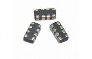
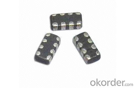
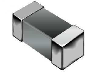
SMD Multilayer Ferrite Chip Bead 0805
- Ref Price:
-

- Loading Port:
- China Main Port
- Payment Terms:
- TT or LC
- Min Order Qty:
- 4000 Pieces pc
- Supply Capability:
- 4000 Pieces per Day pc/month
OKorder Service Pledge
OKorder Financial Service
You Might Also Like
1.SMD multilayer ferrite chip bead
2.High Impedance Characteristics
3.size: 0805
4.RoHs
5.competitive price
Features:
*Low crosstalk/DCR, high reliability
*Low crosstalk between adjacent circuits
*Single MZA series chip provides noise attenuation for four lines, ideal for various highly miniaturized I/D lines
*Internal electrodes feature low DC resistance, minimizing wasteful power consumption
*Electroplated terminal electrodes accommodate flow and reflow soldering
*Mololithic structure ensures high reliability
*Operating temperature range from -25 to 85℃
Applications:
*High-frequency noise counter measured in computer
*Printers
*Portable telephones and other equipments
*VCRs
*Televisions
- Q: An inductor is formed by winding a coil on a limb of a ferromagnetic core. What would the core losses be in a coil-core assembly excited by a DC current? Explain why.
- Core losses are a function of frequency raised to about 1.8. There is no core loss at DC.
- Q: a pure inductor in an a.c. circuit, the rate of change of current with time can be obtained by using calculus and differentiating the current equation.can you explain me how get this equation step by step
- For a linear inductor with no resistance EL di/dt, by definition and fundamental physics. From this, integral(di)i(1/L)integral(E dt)
- Q: A battery, switch, resistor, and inductor are connected in series. When the switch is closed, the current rises to half its steady-state value in 2.0ms.How long does it take for the magnetic energy in the inductor to rise to half its steady-state value?My work:the time constant for the circuit is: L/R 2.9ms-I used the equation i(t) E/r ( 1 - e ^ -RT/L)It asks for time it takes for Magnetic Energy of inductor to rise to half its steady-state value.and the only equation i know that works is U .5LI^2 but i cant use it since i dont know L or I.Please help.
- U (0.5) LI^2 (1) Question is to find time when it becomes U/2 Now from the above equation, you can find I when U becomes U/2. Let it be I' U/2 (0.5)LI'^2 (2) Taking ratio of (1) and (2), 2 (I/I')^2 I' I/√2 Now we have to find time when I becomes I/√2 given that I becomes I/2 in 2 minutes I/2 E/r [1 - e^(2/2.9)] and I/√2 E/r [1 - e^(t/2.9)] Taking ratio, √2 [1 - e^(t/2.9)] / [1 - e^(2/2.9)] 1 - e^(t/2.9) √2 [1 - e^(2/2.9)] - 1.40 e^(t/2.9) 2.40 t (2.9) ln (2.40) 2.54 minutes.
- Q: I think I understand this more now after looking at my notes a little more. I need to turn them into polar form to make the division easier. Then I can put it back into the original form after.
- The magnitude of the circuit impedance is equal to the inductive reactance provided by the inductance: L X ωL, but ω 200 rad/s so that X 200(0.25) 50 ohm while V 100 volts the phasor current for the circuit: I V/Z where V is the voltage phasor V 100 angle 0? and the complex impedance: Z jX j50 Therefore: I 100/(jX) -j2 2 angle -90? The phasor current lags the phasor voltage by 90?.
- Q: I want to use this in an induction motor. (not a rotary phase inverter)
- Nope. Three phase is composed of three waves 120 degrees apart. Inductors can cause a 90 degree shift, but only between the current relative to the voltage.
- Q: does it slow down the current or stops the current into the coil?
- An inductor tends to oppose a change in current, but it doesn't stop. The current through an inductor is given by i(1/L) integral(v dt). In other words an inductor integrates the voltage across it.
- Q: and what do you think its should resistance be
- An inductor is a device that stores energy in a magnetic field. This can be a wire bent to be the shape of a coil. It has a feature called inductance which is separate from its resistance. Its resistance is simply the resistance of the wire used to make it - which is very low and ideally zero.
- Q: if i have coupled inductors with mutual inductance M ,how would i go about replacing them with 1 equivilant inductor and what would be its value ?
- An equivalent single X value for the two initial inductances X1and X2, having mutual inductance M, very much depends on how X1 and X2 are connected into a circuit and upon how X is to be connected. There is not a unique answer independent of circuit connection.
- Q: Has it something to do with the number of windings? I am not sure?
- They don't oppose current flow with resistance but with an opposed voltage. An ideal inductor has no resistance. And it's not the current itself that is opposed but any change in the current. When an inductor is connected to a battery, the current does not rise instantaneously; it's limited to a certain rise rate because the opposing voltage reduces the net voltage driving the the rise. Increasing current in the windings creates an increasing magnetic field which in turn induces an opposing voltage proportional to the field increase rate. This results in an equilibrium between current increase rate and net voltage across the inductor.
- Q: i cant say no lol
- Damn that scandal that you found yourself smack dab in the middle of 15 minutes ago! I never believed it anyway. You and that Bieber chick playing Nude Twister on top of Wal*Mart? Never boughtnever bought it.
1. Manufacturer Overview
| Location | Guangdong,China (Mainland) |
| Year Established | 2010 |
| Annual Output Value | US$10 Million - US$50 Million |
| Main Markets | North America; South America; Eastern Europe; Southeast Asia; Africa; Oceania; Mid East; Eastern Asia; Western Europe |
| Company Certifications | ISO 9001:2000 |
2. Manufacturer Certificates
| a) Certification Name | |
| Range | |
| Reference | |
| Validity Period |
3. Manufacturer Capability
| a) Trade Capacity | |
| Nearest Port | |
| Export Percentage | 41% - 50% |
| No.of Employees in Trade Department | |
| Language Spoken: | |
| b) Factory Information | |
| Factory Size: | |
| No. of Production Lines | |
| Contract Manufacturing | OEM Service Offered Design Service Offered Buyer Label Offered |
| Product Price Range | |
Send your message to us
SMD Multilayer Ferrite Chip Bead 0805
- Ref Price:
-
- Loading Port:
- China Main Port
- Payment Terms:
- TT or LC
- Min Order Qty:
- 4000 Pieces pc
- Supply Capability:
- 4000 Pieces per Day pc/month
OKorder Service Pledge
OKorder Financial Service
Similar products
Hot products


Hot Searches
Related keywords

