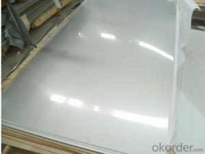
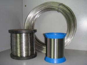
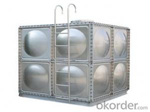
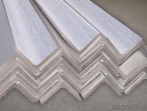
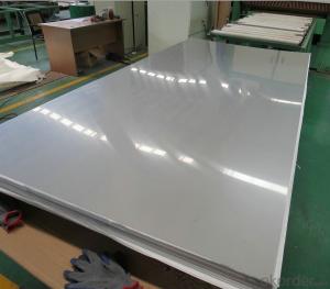
18ga Stainless Steel

Hot Products

FAQ

I am trying to replace the window switch for the driver side and forgot the order of the wires. Can anyone hlep me.
Check out the link below. This is actually for the replacement of the window motor for the 4th gen. f-bodies. But, it does show picz of the switch and the wires leadin to the switch. Good luck!
A load of 125 kip is being held by 3 wires all going up. The Wire one goes straight from the load to the horizontal. Wire 2 and 3 form a V on top of wire 1 and are 30 degrees from wire 1. This is a 2-D problem.
You need to use summation of forces. Wires 1 and 2 are gonna have the same tension on them, just in opposite directions. so in the x direction, Fx=125cos(30)+125cos(150) (the vertical wire doesn't contribute to the x-direction forces and I choose 150 because the wire on the left really has an angle of 180-30 or 150) in the y direction, Fy=125sin(30)+125sin(150)+125sin(90) (The vertical wire is a 90 degree angle) Tension=sqrt( Fx^2 + Fy^2 )
trying to find the radio wiring diagram for my suburban to find out where all my speaker wires are .
1994 Chevrolet Suburban Car Stereo Radio Wiring Diagram Radio Constant 12V+ Wire: Orange Radio Ignition Switched 12V+ Wire: Yellow Radio Ground Wire: Black Radio Illumination Wire: Gray Radio Dimmer Wire: Brown Radio Antenna Trigger Wire: N/A Radio Amplifier Trigger Wire: N/A Front Speakers Size: 6 1/2″ Speakers Front Speakers Location: Doors Left Front Speaker Wire (+): Tan Left Front Speaker Wire (-): Gray Right Front Speaker Wire (+): Light Green Right Front Speaker Wire (-): Dark Green Rear Speakers Size: 6 1/2″ Speakers Rear Speakers Location: Rear Doors Left Rear Speaker Wire (+): Brown Left Rear Speaker Wire (-): Yellow Right Rear Speaker Wire (+): Dark Blue Right Rear Speaker Wire (-): Light Blue
When I cross the black wire and ground I get a spark. Isnthis normal?
This Site Might Help You. RE: in house wiring, why is the black wire hot? When I cross the black wire and ground I get a spark. Isnthis normal?
But when I look closely (you can't see it in the picture unfortunately) there are some tiny wisps of the coiled copper wire that looks as if it could have been connected to the pulled wire. I'm not sure.How do I connect the wires to make the headsets work again?If you guys need more pictures, please tell me.Thanks in advance!
don't be afraid to cut the wires, those wires are no good, strip out a fresh strand of wire, just make sure you remember the color coding of the contacts before you cut the wires, be warned though, working with earphone wires can be tricky, the solder is very hard to bind on the tips of the wires and the fibers are a pain, if you know how to solder then that's fine, but if you don't ask help from someone who can
I removed my old door chime/bell a few years ago and replaced it with a wireless one. That one quit working and now I am attempting to install a new wired one again. The only problem is, when I removed my old one way back, I failed to label the existing wires to where they go. I have two wires coming out of my wall mount, one white, one brown and the both have a white and red wire sticking out of them. I am not sure which one/ones will connect to the FRONT and TRANS posts on my new chime. I don't have a rear door bell button so that is not a problem. Which wire goes to the FRONT and TRANS and do I cap off any of the 4 wires? My installation instructions don't cover the mindless mistake of not having the wires labled.
one wire is coming from the door bell and on is going to a transformer, all you have to do is make it into a series circuit, connect the two red wires together from each cable take one white wire and hook to trans on the door bell and the other to the front. if you want to check this out you need a meter set it for AC under 100v check each set of wires for 12-24v red to white at each cable the one that dosent have power is going to the button at the door while button is pushed check this wire for continuity if this all checks about than wire as i described above
Replaced the old fan in my bathroom (about 10 years old) with a new fan. Trouble is this. The fan and light each work on a seperate bathroom switch. I have two spots to install the wire on the new bathroom fan/light. One for the fan and one for the ligth. However, the wiring has one white, one black, one red and the ground. Anyone know what the red is? Can I just cap it off? According the bathroom fan wiring it says something about connecting red to blue. I am slighty confused. I think it was originally only wired between the white and black. I am not sure if I have to get some extra wire and connect the black and red to the light and the white to the fan? Extra wire is confusing.
The wiring for the original installation had the white wire for a common neutral, and one of the red or black wires for the fan and the other for the light. If your new fixture does not have both a fan and a light, simply use either the red or black, and put a wirenut on the unused wire; you will then have one wall switch that does nothing. If it DOES have both, then one non-white wire goes to the fan, the other to the light, and the white wire goes to both.
I'm trying to install an aftermarket radio in my 2005 suzuki forenza, but it isn't working. The display on the radio doesn't even light up. I'm thinking that it is because there are some unused wires on the oem harness. There is no plug on the original harness thanks to a previous owner, so an adapter plug is out of the question, so i just need to know what wires should or should not be connected to what other wires. The ones which have no equivalent on the aftermarket radio are: illumination wire, and dimmer wire. If someone could provide some info, that would be awesome. The radio being installed is a sony cdx-gt57up.
Suzuki Wiring Harness