
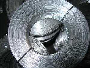


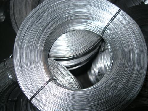

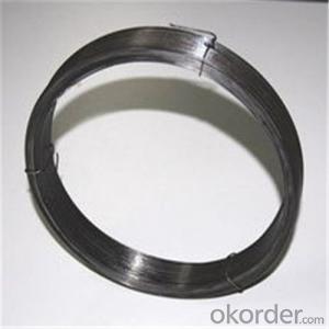
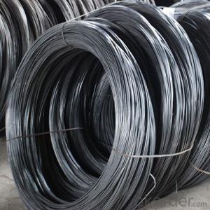
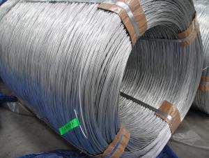
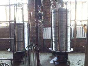
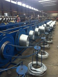
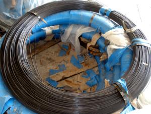
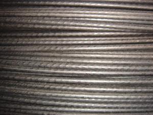
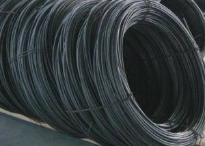
Standard Hot Dipped Galvanised Wire
- Ref Price:
-

- Loading Port:
- China Main Port
- Payment Terms:
- TT OR LC
- Min Order Qty:
- -
- Supply Capability:
- -
OKorder Service Pledge
OKorder Financial Service
You Might Also Like


Commercial Galvanized Steel Wire
(1) Quality : Meet GB/T 343 standard and other requirements of relevant standards .
(2) Zinc Coating: Meet GB/T 15393 standard and other requirements of relevant standards .
(3) Raw Material : Wire rod ——1006 , 1008 , 1018 , Q195 , etc, and zinc with 99.995% purity.
(4) Tensile Strength Range
Size (mm) | Tensile Strength (mpa) |
0.15-1.60 | 290-550 |
0.65-1.60 | 400-550 |
1.61-6.00 | 400-1200 |
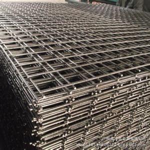
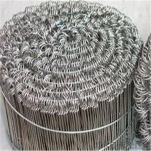
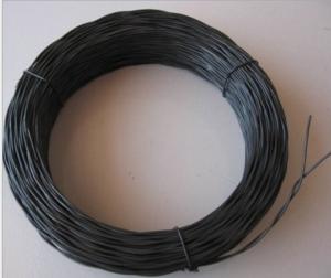
(5) Application : Used in wire mesh , artware , metal hose , binding for agriculture and construction , etc.
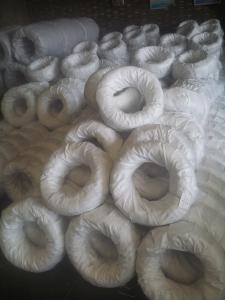
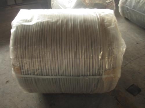
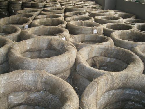
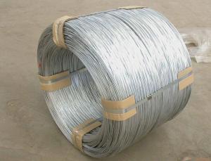
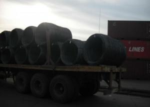
(6) Packing
Size (mm) | Coil Size | Spool Packing | Big Coil Packing | |
ID (mm) | OD (mm) | |||
0.15-0.26 | 6 inch | 1-14kg/spool |
|
|
0.27-0.60 | 8 inch | 1-100kg/spool |
|
|
0.61-1.60 | 12/14/16 inch | 1-100kg/spool | 250-400 | 400-770 |
1.61-6.00 |
| 14-500kg/spool | 450 | 800 |
508 | 840 | |||
(7) Zinc Coating
Meet GB/T 15393 standard.
Size (mm) | Weight of Zinc-Coating ( g/m2 ) | |||||||
A | AB | B | C | D | E | F | ||
A1 | B2 |
|
|
|
|
|
| |
≤0.25 |
|
| 30 | 20 | 18 |
|
|
|
>0.25-0.40 |
|
|
| 30 | 25 | 20 |
|
|
>0.40-0.50 |
|
|
|
| 30 | 20 |
|
|
>0.50-0.60 |
|
|
|
| 35 | 20 |
|
|
>0.60-0.80 | 120 | 110 |
|
| 40 | 20 |
|
|
>0.80-1.00 | 150 | 130 |
|
| 45 | 25 |
|
|
>1.00-1.20 | 180 | 150 |
|
| 50 | 25 |
|
|
>1.20-1.40 | 200 | 160 |
|
| 50 | 25 |
|
|
>1.40-1.60 | 220 | 180 |
|
| 50 | 35 | 30 |
|
>1.60-1.80 | 220 | 180 |
|
| 70 | 40 | 30 |
|
>1.80-2.20 | 230 | 200 |
|
| 80 | 50 | 40 |
|
>2.20-2.50 | 240 | 210 |
|
| 80 | 55 | 40 |
|
>2.50-3.00 | 250 | 230 |
|
| 90 | 70 | 45 |
|
>3.00-4.00 | 270 | 250 |
|
| 100 | 85 | 60 | 30 |
>4.00-5.20 | 290 | 270 |
|
| 110 | 95 | 70 | 40 |
>5.20-6.00 | 290 | 270 | 245 |
| 110 | 100 | 80 | 50 |
- Q: Currently I have the two wires no ground wire and some two wire with ground outlets (upgrade some time before). Is it allowed in the NEC to run a separate ground wire from one of the two wire with ground outlet to the two wire outlet without changing the old wires?
- It isn't allowed to ground the new 'grounding' receptacle to another receptacle on another circuit (if that is what you are asking) Other than that, it IS allowed to be grounded to an accessible point on the grounding electrode system (metal cold water pipe or wire connected to it), the system grounding electrode (ground rod, etc.), the ground bar in the panel from which that circuit originates, or the grounded conductor bar in the panel which the circuit originates (neutral bar). The only other legal option is to install a GFI and label it No Equipment Ground. You can connect downstream receptacles to that same GFI, but cannot connect a ground wire from the GFI to any downstream receptacles and they too must be marked No Equipment Ground and GFCI Protected. The way a GFI works is quite simple. If the current on the hot and neutral conductors isn't the same (within 5mA), it trips. So if there is a different path from hot to anything other than neutral, it will trip.
- Q: why use a large gauge spark plug wires
- What is High Tension Electricity? In all my engineering classes, never heard of it. I wouldn't use large gauge spark plugs unless they were specified. If you use them and they're not specified, you could ruin the spark plugs for too much voltage.
- Q: We added an AC to a preexisting sx 80 furnace and we are having a hard time wiring the new thermostat to the furnace, and the condensor to the furnace. Anyone know how to get a wiring diagram?? thanks
- Onewire Armstrong
- Q: I have this ipod cord in my car to play music off of, and at first it started cutting out. I would move the wire in a specific spot to a position to where it would work. Then eventually it just stopped working all together, so im assuming the wires inside have been damaged. Now as i said before in a specific spot so im pretty positive i know where it is broken at, but ive never actually spliced a wire, or soldered before. This is where i need help. What tools and materials will i need to fix the wire? Also, how would i fix it? Thanks for the help in advance!
- The wires in those little patch cords and headphones and stuff are often very fine and hard to splice or solder. You could get you some wire cutters and wire strippers and a soldering iron and some electrical tape or shrink wrap and go at it, but it would probably be just as well to get another cord.
- Q: i know nothing about wire. thanks. :|
- Solder wire has a lower melting point, allowing you to melt it onto something else. In it's wire form, it will also snap very easily. (not good for fastening things together). Mechanical wire (I'm assuming electrical wire), is designed to withstand high temperatures (and hence, electrical currents), and are usually be bent much more. It's also usually sheilded in rubber (e.g. electrical cords, computer cables, coxial (tv) cable, etc).
- Q: My renter took apart a timer that was hooked to a ceiling fan because the timer was clicking loudly.Now, I just want to simply install a normal on/off switch in it's place. There are two sets of wires coming into the box. One set has a red,white, and black wire coming from it. The other set has just a white and black wire coming into the box. I'm sure this is relatively simple for someone who has wiring expertise. How do I wire a normal light switch to these wires?!?!
- The set of black and white wires are coming from your breaker box (supply). The Black, white and red wires are leading to your ceiling fan (demand). This next part depends on how your fan is wired up. You will want to check first. USUALLY, the red wire controls the fan only, while the black wire supplies power to the light kit, but it could be reversed. This is the part that you want to check. The red wire may also be capped off in the ceiling box and only exists if the user wants separate fan/light control in the future. Assuming that the red wire is capped off: 1.) Turn off the breaker supplying the circuit you are working on. 2.) Use a wire nut to twist the white wires together. 3.) Use a second wire nut to cap off the red wire. 4.) Wrap the black [supply] wire clockwise around the bottom screw on your new switch and tighten.. 5.) Wrap the black [demand] wire clockwise around the top screw on your new switch and tighten. 6.) Attach the new switch to the wall box while carefully tucking the wires in behind the switch. 7.) Install cover plate. 8.) Restore power to the circuit. It IS possible that the person who installed the ceiling fan used the red wire as the hot instead of the black. If this is the case, you can either rewire the ceiling fan's box accordingly (disconnecting the red wire and using the black instead) or substituting red instead of black in the instructions above. The red wire would then connect to the top screw terminal of your switch. If the red is connected to the light kit (if applicable) and the black is connected to the motor (or vise versa), disconnect the light kit and wire it along with the motor.
- Q: installing whelen car strobe lights.the directions say to wire the power to the battery with wire that can hold 125% of the power
- use one that is larger than what is used going to the strobes. the less the resistance the better and brighter the strobes will perform. and it is a good idea to ues a relay.
- Q: Suppose we have a 10v battery.one end of the battery is at 10V electric potential and other is at 0V Hence,the potential difference is 10V.if we measure the voltage( p.d.) across positive terminal at 10V and the middle of the wire connecting both ends of battery will it be less??I mean,at the middle of the wire the electric will not be zero,right??(correct me if am wrong)Thanks!!
- If the wire had some reasonable resistance which prevented melting of the wire and explosion of the battery; the middle of the wire would show half the potential difference between the terminals. The wire connecting the terminals becomes a potentiometer with Voltage falling linearly between the terminals (assuming uniform resistance along the length of the wire). In practice, Voltage drop on a wire supplying power to a load is proportional to the resistance of the wire divided by the resistance of the load. When the wire is the load, all Voltage drop occurs along the wire.
- Q: I have a kicker cvr 12 inch 2 ohm dual voice coil sub (400 watts) and a kicker zx750 amp. how to wire?
- the present passing interior the process the wires will reason the wires to warmth up if no longer adequate guage. think of of the tens of millions of little electrons pushing and shoving to and fro, all this action motives friction on a molecular point and of course all of us comprehend friction equals warmth. In an even bigger guage cord there is extra area for the comparable variety of electons. that is rather that straightforward. Use as heavy a guage speaker cord which you would be able to. you will haven't any sign loss and little warmth.
- Q: Okay so my question is how would I wire these in a ported box with 2 terminals on each side of the box? Also, is the quot;Bridged Wirefeatured in the diagram negative speaker wire? Thanks.
- It's a misnomer to use the term bridged in wiring subs. They should call it a jumper wire, or something similar. It's a minor detail, but it leads to novices thinking bridging is something done with subs -- it's not, it's the amp. Although since mono amps are becoming more and more common bridging is becoming a thing of the past as mono amps aren't bridgeable. The way I would do it would be to wire each sub to its respective terminal with the coils in series for 4 ohms.
Send your message to us
Standard Hot Dipped Galvanised Wire
- Ref Price:
-
- Loading Port:
- China Main Port
- Payment Terms:
- TT OR LC
- Min Order Qty:
- -
- Supply Capability:
- -
OKorder Service Pledge
OKorder Financial Service
Similar products
Hot products
Hot Searches
Related keywords

