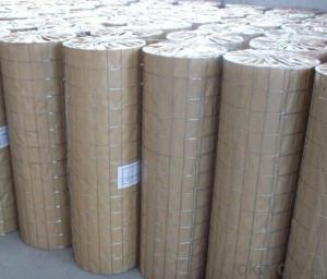
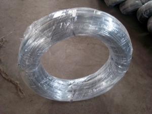
Hot Dipped Galvanized Welded Wire Mesh Roll
- Ref Price:
-

- Loading Port:
- Tianjin
- Payment Terms:
- TT OR LC
- Min Order Qty:
- 4 m.t.
- Supply Capability:
- 100 m.t./month
OKorder Service Pledge
OKorder Financial Service
You Might Also Like


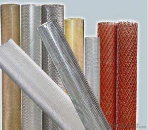
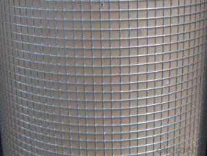
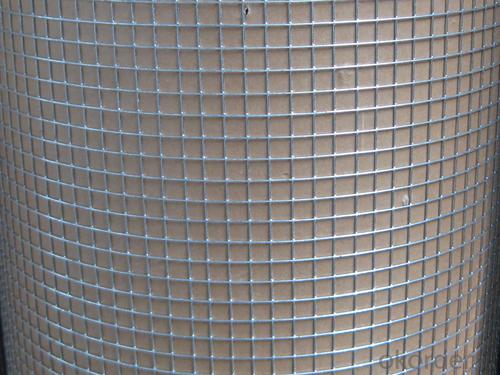
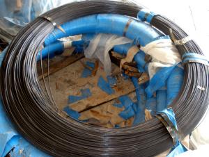
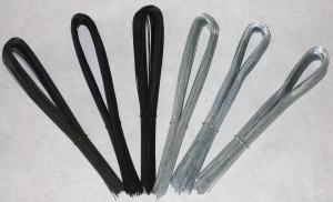
Welded Wire Mesh
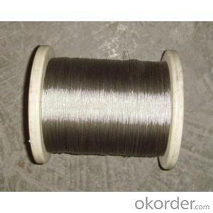
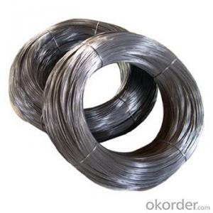
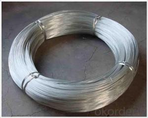
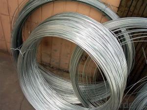
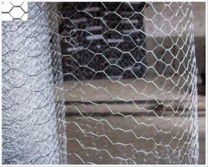
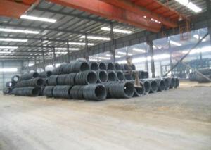
1.Material:
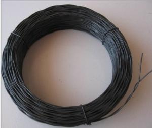
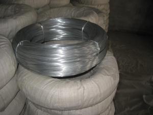
superior low carbon steel wire, galvanized wire , stainless steel wire,PVC coated wire
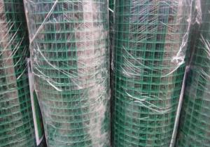
2.Surface treatment:
electro-galvanized, hot-dipped galvanized, PVC coated
3.Manufacture process:
The galvanized electric wire mesh, welded after galvanized electric welded mesh and plastic coated mesh are made with high-quality iron wire by automatic equipment.
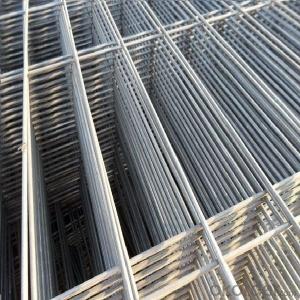
4.Feature:
smooth mesh surface ,well proportioned meshes,strong welded points and bright luster . The mesh doesn’t come loose even if cut in parts or being exerted force on parts .Compared with general iron wire ,the products are better in respects of anti-corrosive and anti-rust .
5. Usage:
It is widely used in industry, agriculture, construction, transportation,mining etc
6. Specification List
(Standard welded wire mesh)30m length,width 0.5m-1.8m | ||
hole size | wire gauge(BWG) | |
inch | mm | |
1/4" x 1/4" | 6.4 x 6.4 | 22,23,24 |
3/8" x 3/8" | 10.6 x 10.6 | 19,20,21,22 |
1/2" x 1/2" | 12.7 x 12.7 | 16,17,18,19,20,21,22,23 |
5/8" x 5/8" | 16 x 16 | 18,19,20,21, |
3/4" x 3/4" | 19.1 x 19.1 | 16,17,18,19,20,21 |
1" x 1/2" | 25.4 x 12.7 | 16,17,18,19,20,21 |
1-1/2" x 1-1/2" | 38 x 38 | 14,15,16,17,18,19 |
1" x 2" | 25.4 x 50.8 | 14,15,16 |
2" x 2" | 50.8 x 50.8 | 12,13,14,15,16 |
( PVC coated welded wire mesh)30m length,width 0.5m-1.2m | ||
hole size | wirre gauge(BWG) | |
inch | mm | |
1/2" x 1/2" | 12.7 x 12.7 | 16,17,18,19,20,21 |
3/4" x 3/4" | 19 x 19 | 16,17,18,19,20,21 |
1" x 1" | 25.4 x 25.4 | 15,16,17,18,19,20 |
- Q: I have a water valve that I need to connect but I don't know how to read this diagram. I'm unsure how to connect the wires to the cold and hot valve. I have four wires that need to be connected. A pair of white caps with one blue wire and one orange; and a pair of black caps with one blue wire and one yellow wire. Sorry if this sounds confusing but I have no idea how to explain it well. Thanks!
- Oddly the diagram shows three valves, a hot and two cold valves. If you were needing to wire Cold Valve 1 and Cold Valve 2, the wire colors you describe are shown as one or two letters in front of the connector IDs (where BL presumably means blue, and O and Y, orange and yellow).
- Q: Two current carrying wires are perpendicular to each other.Wire 1 is placed on top of wire 2.Wire 1 current direction is pointing North, wire 2 current direction is pointing east. Is there a force on either of the two wires?Does one wire spin due to the produced force?Please explain to me how to do this questionThanks
- Take your right hand and point its thumb to the North representing conventional current flow (Plus to Minus) in the top wire. Visualize the curl of your right hand's fingers can now be replaced be visualizing a bike tire rotating from nuckles to fingernail. Now do the same with the wire having current going East. Contact the two bike tires together a some infinitesimal spot. If those tires are exactly perpendicular in the X and Y (Z doesn't seem to matter because it is the point where they touch), it would make sense to predict that on top a vector will point West and on the bottom a vector will point South. The net vector should be SW. So, if you marked the initial point of cross over on the wires and mechanically could keep them free to move but still perpendicular, the cross over point would move SW for as long as equal current flowed in the two wires.
- Q: four lead black wire coming from fan coil motor for a recessed wall unit; ribbed on one side, smooth on the other side, and two flat sided wires in between. Which wire would be common and which wire would be hi, med, and lo?
- Need more info. What voltage ? Different colors on wires? White usual indicates common or the neutral. Black is your hot for 120 usuAlly. Hi med And low Are power settings on the fan I don't believe ud have to wire them seperatly. Repost this with more specific info and I'll answer it. I'm an electrician And have a master electrician with me so if u give more info I can help.
- Q: wire is 4.5 ft from the pole. (a) How much wire is used? (b) How high up the pole is the wire connected?
- Wire length = 4.5' / cos 80 degrees = 25.91 feet Distance up the pole to where the wire is connected = 4.5' (tan 80 degrees) = 25.52 feet
- Q: I'm trying to fix a light fixture for a friend. Her father-in-law gummed it up. At the fixture, there are 3 white wires soldered to a single wire. There are 3 black individual wires and one red wire. There are three switches that control the light.If I hook one of the black and the 3 white to the light, the light stays on constantly. If I hook either of the two other black individually, nothing comes on period.I'm pretty much at a loss. Any advice would be greatly appreciated.
- USA Sounds to me that what you have is 1 two conductor (black/white) cable as a power feed, 1 two conductor tap taking power somewhere else, and 1 three conductor (black, white, red) taking power to and back from a switch. All the whites get joined together, with a pigtail to the light. Make sure you have a tester. Find the black wire that is always energized, and mark it. Find the black and red that are in the same cable; mark them. I think what you have is they ran power to the light instead of the switch, then took the power down to the switch on the black conductor, and back from the switch to the light on the red conductor. Take the black that is always hot, and splice it to the other two blacks. Do not take it to the light. Hook the red to the light. If this does not work, reverse the red and black that go to the switch. This will take power to the switch on the red, and back from the switch on the black.
- Q: I was looking at the wiring of my current thermostat and I want to know why it's wired the way it is...The yellow wire was wrapped around the white terminal and the yellow terminal. And the white wire was wrapped the around the Orange terminal. The red and green wires were each wrapped around their respective terminals. And the blue wire wasn't connected to anything. Why would the electrician have wrapped the yellow wire around 2 terminals? Is that normal? Also, I tried installing a new thermostat but the heating is not working. The fan works but it just blows room temperature air. The new thermostat only had 4 terminals for R, Y, W, G. I connected the wires I had to their respective terminals. However, I think it may not be working because I have a probably have a heat pump. Any Ideas why else it might not be working? Thanks a lot!
- If you have a heat pump, then the thermostat that you currently have will not work. Otherwise, green wire to G, (fan circuit) white wire to W (heat circuit) Yellow or Blue to Y (cooling circuit) but don't hook up both. Just one or the other. Finally, Red to RC/RH (24V circuit). Make sure on your furnace control board that it is wired the same as your T-stat. Good luck.
- Q: i have a 2004 Isuzu Rodeo I cannot find the wiring harness color codes for it. i need the Left Rear positive negative colors the Right Rear positive negative colors. Thank You.
- GOOD LUCK... Isuzu cars and trucks are discontinued and the only Isuzu dealers still opened are big trucks like the NPR box trucks... unless you find someone online like a former Isuzu tech, not sure if you will get any schematics
- Q: what wires connect from the vehicle to the a/f sensor
- Why do u want to know what wires go to the sensor? If you have a code for the a/f sensor..99 % of the time it is an open in the sensor itself. On rare occasion there are others like a chewed wire by a rodent. But I would just recommend replacing the a/f sensor. And i u were to follow the wires from the male connector they would lead you to a big wire harness that basically just all ends up at the ECU. Just in case u wanted to know.
- Q: I'm installing a remote start system in my car, but I can't find the tach wire. Does anyone know what harness it is located in, and what color the cable is? I've looked over the diagrams, but I can't seem to find the cable that runs to the tach guage.
- You can use a wire from a fuel injector. They should have two wires. Look at all of them and use a wire that is NOT common to other injector wires.
- Q: Ok so I bought a blower and barrow at the junk store... Figured I could use a v-belt to drive it with this old motor I have... Homemade dust collector!!! Anyhow I have no Idea how to wire it up... I know it probably needs a capacitor but thats about it... It's an Emerson... Has orange, blue, brown, white, and black. Any Ideas would be great! On the sticker it list three different speeds (rpms) So i'm guessing I don't need all the wires and some are just quot;taps.quot;
- i think of you have enormously plenty responded your individual questions. The drain is clogged as they generally get with out each year maintenance or a minimum of two times a summer season pouring bleach in the path of the line. And besides, it has probable broken the blower motor. One issues for specific although, by no ability attempt and repair the unit or look at it with out first turning the capacity off to the kit which it variety of feels which you ignored to do. I additionally undertaking to assert that somebody has at one time replaced that blower motor because of the fact your description of the wires might point out that it wasnt production facility set up anymore.however the provider tech which you will might desire to call and time table an appointment with would be waiting to repair and replace mandatory aspects. go away something as much as the pros
Send your message to us
Hot Dipped Galvanized Welded Wire Mesh Roll
- Ref Price:
-
- Loading Port:
- Tianjin
- Payment Terms:
- TT OR LC
- Min Order Qty:
- 4 m.t.
- Supply Capability:
- 100 m.t./month
OKorder Service Pledge
OKorder Financial Service
Similar products
Hot products
Hot Searches
Related keywords

