


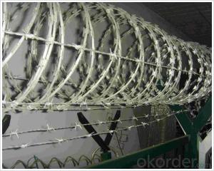
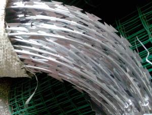
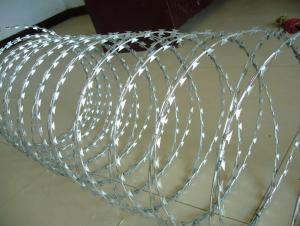
High Quality Galvanized Razor Wire With Electro Dipped Galvanized Wire
- Ref Price:
-

- Loading Port:
- China Main Port
- Payment Terms:
- TT OR LC
- Min Order Qty:
- -
- Supply Capability:
- -
OKorder Service Pledge
OKorder Financial Service
You Might Also Like


Quick Details
Packaging & Delivery
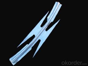
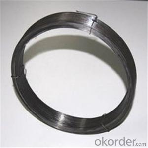
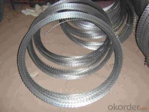
SpecificationsBlade thickness:0.5mm
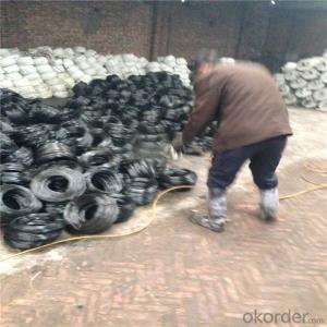
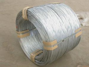
razor wire Razor barbed tape is a kind of modern security fencing materials fabricated with razor-sharp steel blade and high-tensile wire. Razor Wire Variety:
| |||||||||||||||||||||||||||||||||||||||||||||||||||||||||||||||||||||||||||||||||||||
- Q: I need the wiring codes for a factory radio to install a new one.
- 1993 Toyota Paseo Car Radio Wiring Diagram Car Radio Battery Constant 12v+ Wire: Blue/Yellow Car Radio Accessory Switched 12v+ Wire: Gray Car Radio Ground Wire: Brown Car Radio Illumination Wire: Green Car Stereo Dimmer Wire: N/A Car Stereo Antenna Trigger Wire: N/A Car Stereo Amp Trigger Wire: N/A Car Stereo Amplifier Location: N/A Car Audio Front Speakers Size: 4″ Speakers Car Audio Front Speakers Location: Doors Left Front Speaker Positive Wire (+): Pink Left Front Speaker Negative Wire (-): Purple Right Front Speaker Positive Wire (+): Green Right Front Speaker Negative Wire (-): Blue Car Audio Rear Speakers Size: 6 1/2″ Speakers Car Audio Rear Speakers Location: Rear Deck Left Rear Speaker Positive Wire (+): Black Left Rear Speaker Negative Wire (-): Yellow Right Rear Speaker Positive Wire (+): Red Right Rear Speaker Negative Wire (-): White gl ........
- Q: I am replacing an electrical outlet that currently has 3 white and 3 black wires plus the ground wire. The bad outlet has 3 holes already in it for each of the wires but my new outlet does not, there are only 2 holes and/or the 2 screw on each side. How do I install this new outlet? Do I need to do the pigtail here?
- For the best answers, search on this site https://shorturl.im/awtUt Try this. take the plug out of the box, so that just the 7 wires are hanging there. Of course, your power is off before you do this. Take the 3 white wires and twist all their copper ends together. Then flip the breaker on. If the breaker does not trip, most likely those white wire are all neutral. If the breaker does trip, one of those white wires is being used as a hot (black) wire. If the breaker did not trip, turn the breaker off again. Now twist all 3 black wires together, flip the breaker on. If the breaker does not trip, the black wires all belong together. If the breaker does trip now, one or two of the black wires is being used as a neutral or is coming from a different source, such as another breaker or going through the outlet to somewhere else in the house. If the breakers don't trip either time, all black wires belong together and go on the brass screw of the outlet (or the side with the small opening). All the white wires go on the silver screw (or large opening of the plug). If it doesn't work, you will need an electrical tester to find out which wires are hot or wires that don't belong together because they may be a different voltage. Don't want to confuse you but there may be 220 volts in the plug between 2 of the black wires.
- Q: I want to know what the definition is of a hot wire gauge.
- A hot wire gage is a tool that tells you which wire(s) are hot meaning that they have electricity running through them. If you go to the tool store you would ask for a voltage detector. These are about the size of a pen. They light up and beep when the detect voltage. I highly recommend having one when doing electrical. There is nothing worse than grabbing a wire that you thought was powered off only to get lit up. Hope this helps.
- Q: What's the factors affecting resistance of a wire? and why? thank you!
- The 2nd and 3rd discussions were good but didn't discuss magnetism. The 1st guy: an open circuit has infinite resistance. Even a straight piece of wire has some self-inductance (or self-magnetism). One affect of inductance is that it opposes changes in current. So when you first apply a dc voltage across a wire and a dc current starts to flow, the self-inductance will resist the increase in current. It will appear to be because of higher resistance than expected. But the current will increase over a short time, and once it gets to a steady-state, the apparent resistance from the self-inductance is zero. This, self-inductance in a straight piece of wire, is a minor affect compared to components that presumably are in the circuit. After the current reaches steady state, the self-inductance will try to oppose a decrease in current. If the voltage and therefore the current are ac - alternating, this gets more complicated. The current is always trying to change. At the level of study I think you are, you should save this for later.
- Q: There are two switches – the left is for the fan, the right is for the light. They operate independently. I want to replace the light switch with one that has a motion sensor.There are four sets of bundled wires coming out of the back of the box. Each bundle has a white, a black, and a copper wire.Two black wires come out of each switch. The top wires go into two of the bundles in the back of the box, the bottom wires are connected with each other and with two more black wires coming out of the other two bundles coming out of the back of the box.All the white wires are twisted together with a red cap. All of the copper wires are twisted together with another red cap.My motion sensor has a red, black, green and yellow wire. The directions say the yellow wire is not used, because this is not a 3-way light. Is there a straightforward way to do this?
- Sure is!. You wire it exactly the way the instructions say to. Which is to use the 2 wires on the existing switch. The bare wire on the switch (if present) is the ground and goes to the green. Just like the instructions say. You are apparently letting all those other wires scare you. The motion sensor is nothing more than an automatic switch. It does the same thing the existing switch does, using the exact same wires. Do Not touch any of the existing splices. Look again at the instructions. Take a deep breath and have at. I've been in control cabinets with Hundreds of wires in them. I ignored all but the ones I need to work on. Other wise I would still be there trying to figure it out! (chuckle)
- Q: On a seat switch on a poulan mower it has three wires are two of them grounds or one.
- One wire comes in hot and goes out hot to the next switch in the series of safety switches this is known as the switched pair, and the other wire is the ground, get a ohm meter and see which wires are paired by pushing the switch while in ohm mode when the meter reads 0 ohms when the switch is pushed those are the switched wires.
- Q: Please help. I am trying to fit a new light into a house with old wiring.My new light just has a connection block with 1 blue wire and 1 brown wire. When I removed the old light there are 5 wires coming from the ceiling. 1 black and 1 red coming from one lead and 1 black and 1 red coming from the other. Any ideas how I wire this up. Many thanks.
- You have very old wiring if you only have 2 pairs of black and red wires in the ceiling. A modern installation will contain a third pair and also have green/yellow (or bare copper) earth conductors too. The following instructions will make your light work but you should get your wiring checked as soon as possible to bring it up to modern safety standards. One of the cables in the ceiling is carrying your supply current from the fuse box, the other is coming from the switch. You must connect the red wires together with a secure plastic joint block. This will send Live current down to the switch. Connect one of the blacks to the blue wire in the light fitting. This will make the Neutral connection to the light. Connect the other black to the brown wire of the light fitting. This will be the Live connection from the switch. If you have any green and green/yellow wires then you must connect these together because they are the earths. Make absolutely sure that you thoroughly insulate your joint blocks with electricians tape before you secure the fitting to the ceiling.
- Q: i have a 2004 Isuzu Rodeo I cannot find the wiring harness color codes for it. i need the Left Rear positive negative colors the Right Rear positive negative colors. Thank You.
- GOOD LUCK... Isuzu cars and trucks are discontinued and the only Isuzu dealers still opened are big trucks like the NPR box trucks... unless you find someone online like a former Isuzu tech, not sure if you will get any schematics
- Q: Say you have a 5 cm current wire carrying 10 A going from left to right. Directly 1 c.m below the left end of this wire is a long wire that is perpendicular to the first wire and goes out of the page. What is the net force on the 5 cm wire?I've tried using F=ILB with the I of the first wire and the B of the second wire.
- I didn't read the question so I was carefully working out the force. The wire is perpendicular to the first wire, so using the right hand rule you discover that the field it creates is PARALLEL to the first wire at this left end. The magnetic force is caused by the component which is PERPENDICULAR to the wire which is in fact zero. So there is no magnetic force at this point. As you move along the wire you get a diminishing amount of magnetism caused by the wire which is going out of the page but that field has a component which is DOWN the page. Therefore that part of the wire experiences a force which is into the page. ( take your right hand, put the thumb along the wire pointing to the right, the fingers point down the page, the palm points into the page which is then the direction of the force) I would be surprised if you were required to work out the magnitude of the force in this context. You can't use F= ILB because both the magnitude and the direction of the field varies at different points along the wire. If the perpendicular wire had been directly below the middle of the other wire there would have been no net force. If you were of a level where working out the force was appropriate you would need to set up the formula for B at various points along the wire, taking the vertical component only and integrate this over the range from 0 to 5 cm. Not a trivial mathematical task.
- Q: can you use your existing phone line jacks and wire, then convert the jacks to lan to network computers or printers?
- Yes the difference is that network cable (cat 5) supports 100mbs data transfer and has a range of 100 meters. Network cable is also shielded against R/F interference and uses a connector similar to a phone connector (RJ45) but is bigger. Phone cable is smaller in diameter and in most cases is not shielded it uses a (RJ11) connector. It may be possible to use the phone lines to connect your network but you would have to know how to terminate the ends of the cable. This takes a special tool and also the ability to do it. Its not that easy to do, Its easy if you have some one show you. I've been doing this for years, my advice would be to use network cable, do it right. wireless is the easy way to do it.
Send your message to us
High Quality Galvanized Razor Wire With Electro Dipped Galvanized Wire
- Ref Price:
-
- Loading Port:
- China Main Port
- Payment Terms:
- TT OR LC
- Min Order Qty:
- -
- Supply Capability:
- -
OKorder Service Pledge
OKorder Financial Service
Similar products


Hot products

Hot Searches

