
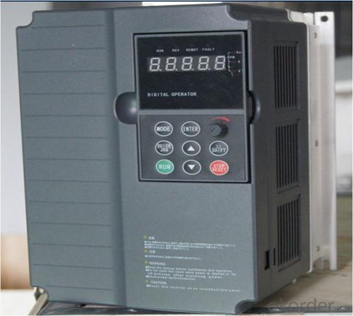
China Best Selling VFD Frequency Drive Three Phase 380V
- Ref Price:
-

- Loading Port:
- Tianjin
- Payment Terms:
- TT OR LC
- Min Order Qty:
- 1 pc
- Supply Capability:
- 100000 pc/month
OKorder Service Pledge
OKorder Financial Service
You Might Also Like
Specifications
1.220V Single Phase Variable Frequency Drive 2.2KW
2.Advanced control technology
3.Easy to operate
220V Single Phase Variable Frequency Drive 2.2KW
General
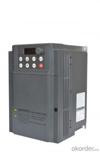
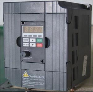
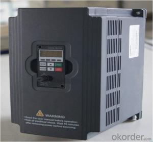
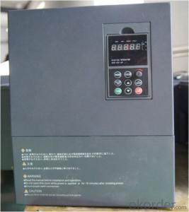
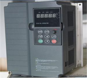
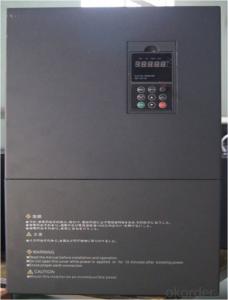
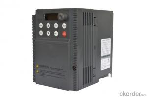
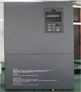
CNBM frequency inverter is a high-quality, multi-function,
low-noise variable frequency drive which is designed, developed and manufactured according to international standards.
It can meet different needs of industrial conditions.
The inverter applies advanced control technology of space voltage vector PWM, with functions of constant voltage control, power-off restart, dead zone compensation, automatic torque compensation, online modification parameter, high-speed impulse input, simple PLC and traverse.
Product Name:CMAX-VCG15/P18.5T3 ~ CMAX-VCG18.5/P22T3
Application
Textile: coarse spinner, spinning frame, wrap-knitting machine, loom, knitting machine, silk-spinning machine, etc.
Plastic: extruder, hauling machine, decorating machine, etc.
Pharmacy: mixer, roaster, etc.
Woodworking: engraving machine, sander, veneer peeling lathe, etc.
Papermaking: single type papermaking machine, etc.
Machine tool: non-core grinding machine, optical lens grinding machine, cutting mill, etc.
Printing: cloth-washing machine, dye vat, etc.
Cement: feeder, air blower, rotary furnace, mixer, crusher, etc
Fan and pump: kinds of fans, blowers and pumps
Specification
Item | Specification | |
Input | Input voltage | 220/380V±15% |
Input frequency | 47~63Hz | |
Output | Output voltage | 0~input voltage |
Output frequency | 0~600Hz | |
Peripheral interface characteristics | Programmable digital input | 4 switch input, 1 high-speed impulse input |
Programmable analog input | AI1: 0~10V input AI2: 0~10V input or 0~20mA input, | |
Programmable open collector output | 2 Output (3.7kW and above: 1 Open collector output) | |
Relay Output | 1 Output (3.7kW and above: 2 Relay output) | |
Analog output | 2 Output, one is 0~10V, another is 0~20mA or 0~10V | |
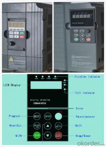
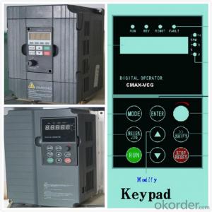
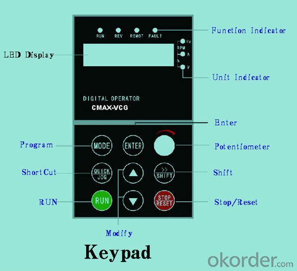
Keypad | Display:5-digit 8-section LED (Red), 2 indicators; parameter setting: 8 keys (including multi-function hot key ), 1 potentiometer | |
Technical performance characteristics | Control mode | All digital space voltage vector SVPWM algorism |
Overload capacity | G purpose: 150% rated current 60s P purpose: 120% rated current 60s | |
Speed ratio | 1: 100 | |
Carrier frequency | 1.0~10.0kHz | |
Torque compensation | Linear, multi-point, 1.3th power, 1.7th power, 2.0th power reduced torque; Compensation voltage range: automatic compensation and manual compensation 0.1~10% | |
Automatic voltage adjustment | It can automatically maintain output voltage constant when grid voltage fluctuates. | |
Automatic current adjustment | When the current is over current limit, under clocking automatically limits output current. | |
Function characteristics | Frequency setting mode | Keypad digital analog input, keypad potentiometer, impulse frequency, communication, multi-step speed and simple PLC, PID setting and so on, switch-over of setting modes. |
Simple PLC, multi-step speed control | 16-step speed control | |
Special function | Traverse control, length control, time control | |
QUICK/JOG key | User-defined multi-function hot key | |
Protection function | Over-current, Over voltage, under-voltage, over-heat, phase failure, over-load and motor over-load | |
Working condition | Installation site | Indoor, altitude of less than 1km, dust free, non-corrosive gases, no direct sunlight |
Application environment | -10°C~+40°C, 20~90%RH (no dew) | |
Vibration | Less than 0.5g | |
Storage temperature | -25°C~+65°C | |
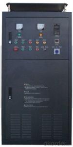
Installation type | Wall-mounted type, floor cabinet type | |
Cooling mode | Air-forced cooling | |
- Q: What's the use of switching frequency of converter?
- Meanwhile, the switching frequency of the converter is adjusted, and the power loss can be adjusted. Because the switching frequency of power loss and inverter power module IGBT is related with the increase in switching frequency inverter and increasing the power loss, this makes the efficiency drop, two is the power module heating increases, is detrimental to the operation, of course work electric converter pressure is high, the power loss also increase effect.
- Q: Knowledge, principle and operation method of frequency converter.
- Sinusoidal pulse width modulation (SPWM) of U/f=C with frequency converter control mode:The characteristics of SPWM inverter control way is to control the circuit has simple structure and low cost, the mechanical properties of hardness is also good, can meet the general requirements of smooth speed transmission, has been widely used in various fields of industry. However, when the output voltage is low, the torque is significantly affected by the stator resistance pressure drop, so that the maximum output torque is reduced. In addition, the mechanical characteristics of DC motor can not hard, dynamic torque capacity and static performance is not satisfactory, and the system performance is not high, the control curve will change with the change of the load torque and motor torque, slow response, low utilization rate is not high, due to the stator resistance and the existence of dead time effect of the inverter performance the poor stability, etc.. Therefore, people have studied vector control frequency conversion speed regulation.
- Q: It was when processing a workpiece, processing spindle stops suddenly (other are normal) a check is, I jump out of the inverter, I can click on a processing, and then processing not long after they happen, (do not open the machine spindle machining will also be the case)
- It should be a frequency converter. Right now, look at the frequency converter output frequency settings, tune, and suggest the next election wide output frequency converter, or simply PLC
- Q: What is frequency conversion? What is the function of frequency converter?
- Power factor compensation, energy savingThe reactive power will not only increase the heating power loss and equipment, more important is to reduce the power factor of the power grid leads to the decrease of active power, reactive power consumption in a large number of lines, low efficiency, serious waste of equipment, the use of frequency control devices, the inverter internal filter capacitor, thereby reducing the reactive power loss, increase active power grid.
- Q: What are the precautions for frequency converter wiring installation?
- The control signal line should not be parallel to the power line. If parallel must be used, the shielding wire and one end of the earth must be used.To use 485 or 232 communication, wear a magnetic ring and use twisted pairs.
- Q: What does "frequency" in household appliances mean?
- The new inverter refrigerator not only the reduction of power consumption, realize mute, and the use of high-speed operation can achieve substantial rapid freezing; in the washing machine, used frequency variable speed control, improve washing performance, washing machine popular in addition to saving energy and silent, still ensure soft clothing washing and other aspects of the introduction of control new content;
- Q: How to maintain the frequency converter will not damage, or regular maintenance?
- 1. cooling fan, inverter power module is the most serious heating device, the continuous heat generated by the work must be promptly discharged, the general fan life of about 10Kh-40Kh. According to the continuous operation of converter for 2-3 years, it is necessary to replace the fan2. filter capacitor, intermediate circuit filter capacitor: also called electrolytic capacitor, its main function is to smooth the DC voltage, absorb the low-frequency harmonic in dc.
- Q: What are the basis of the frequency converter to choose?
- 1. the power of the inverter is selected according to the load power. How many power motors should be chosen for a multi power motor?. Size one is ok.2. frequency converter model, different uses, choose different frequency converter. For example, there are general frequency converter, fan, water pump dedicated inverter, a machine tool spindle dedicated inverter. Wait。3. when the load is large, the braking unit and the braking resistor should be selected simultaneously.4. check the motor nameplate current rating (no nameplate rated current). The rated current of the inverter is greater than the maximum running current of the motor
- Q: Frequency converter OC alarm, what's the matter?
- And some did not inform you of the inverter fault category, when the OC boot failure, will cause greater danger, then simply caused by surface phenomenon similar to program crashes, such as the P9/G9 series machine when the machine detects INVT, module failure, operationThe H00 character appears on the panel, and all key actions are rejected. Unknown insider will think: program crash, CPU motherboard is a problem.
- Q: How to choose frequency converter?
- 3. when the load is large, the braking unit and the braking resistor should be selected simultaneously.4. check the motor nameplate current rating (no nameplate rated current). The rated current of the inverter is greater than the maximum running current of the motor
Send your message to us
China Best Selling VFD Frequency Drive Three Phase 380V
- Ref Price:
-
- Loading Port:
- Tianjin
- Payment Terms:
- TT OR LC
- Min Order Qty:
- 1 pc
- Supply Capability:
- 100000 pc/month
OKorder Service Pledge
OKorder Financial Service
Similar products

Hot products

Hot Searches

