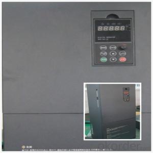
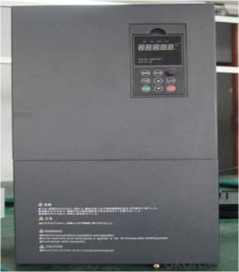
Frequency Inverter 3 phase VFD VSD
- Ref Price:
-

- Loading Port:
- China Main Port
- Payment Terms:
- TT OR LC
- Min Order Qty:
- -
- Supply Capability:
- -
OKorder Service Pledge
OKorder Financial Service
You Might Also Like


Specifications
1.220V Single Phase Variable Frequency Drive 2.2KW
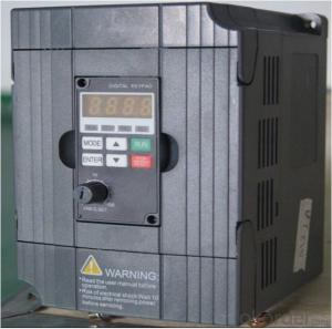
2.Advanced control technology
3.Easy to operate
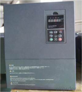
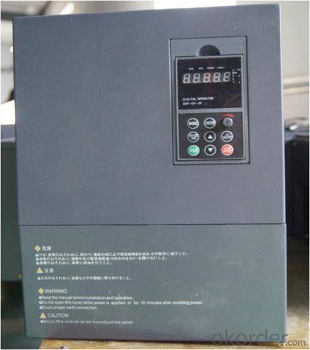
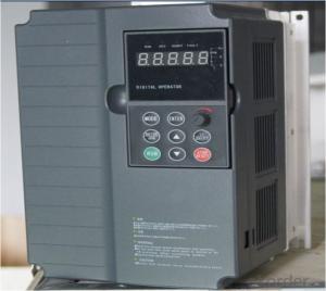
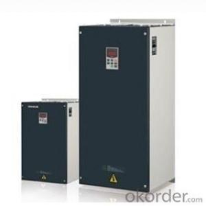
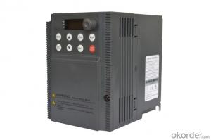
220V Single Phase Variable Frequency Drive 2.2KW
General
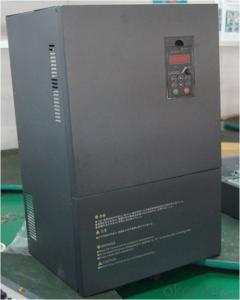
CNBM frequency inverter is a high-quality, multi-function,
low-noise variable frequency drive which is designed, developed and manufactured according to international standards.
It can meet different needs of industrial conditions.
The inverter applies advanced control technology of space voltage vector PWM, with functions of constant voltage control, power-off restart, dead zone compensation, automatic torque compensation, online modification parameter, high-speed impulse input, simple PLC and traverse.
Product Name:CMAX-VCG15/P18.5T3 ~ CMAX-VCG18.5/P22T3
Application
Textile: coarse spinner, spinning frame, wrap-knitting machine, loom, knitting machine, silk-spinning machine, etc.
Plastic: extruder, hauling machine, decorating machine, etc.
Pharmacy: mixer, roaster, etc.
Woodworking: engraving machine, sander, veneer peeling lathe, etc.
Papermaking: single type papermaking machine, etc.
Machine tool: non-core grinding machine, optical lens grinding machine, cutting mill, etc.
Printing: cloth-washing machine, dye vat, etc.
Cement: feeder, air blower, rotary furnace, mixer, crusher, etc
Fan and pump: kinds of fans, blowers and pumps
Specification
Item | Specification | |
Input | Input voltage | 220/380V±15% |
Input frequency | 47~63Hz | |
Output | Output voltage | 0~input voltage |
Output frequency | 0~600Hz | |
Peripheral interface characteristics | Programmable digital input | 4 switch input, 1 high-speed impulse input |
Programmable analog input | AI1: 0~10V input AI2: 0~10V input or 0~20mA input, | |
Programmable open collector output | 2 Output (3.7kW and above: 1 Open collector output) | |
Relay Output | 1 Output (3.7kW and above: 2 Relay output) | |
Analog output | 2 Output, one is 0~10V, another is 0~20mA or 0~10V | |
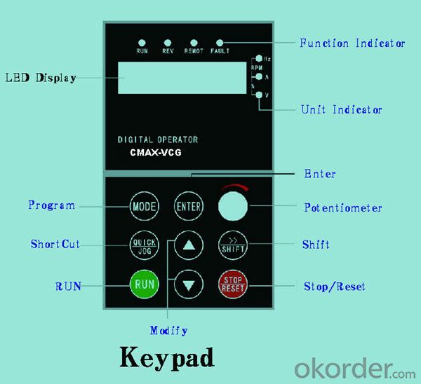
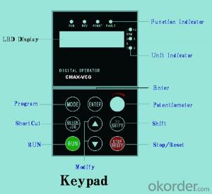
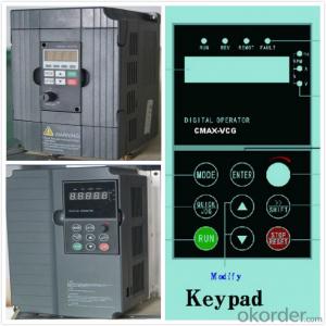
Keypad | Display:5-digit 8-section LED (Red), 2 indicators; parameter setting: 8 keys (including multi-function hot key ), 1 potentiometer | |
Technical performance characteristics | Control mode | All digital space voltage vector SVPWM algorism |
Overload capacity | G purpose: 150% rated current 60s P purpose: 120% rated current 60s | |
Speed ratio | 1: 100 | |
Carrier frequency | 1.0~10.0kHz | |
Torque compensation | Linear, multi-point, 1.3th power, 1.7th power, 2.0th power reduced torque; Compensation voltage range: automatic compensation and manual compensation 0.1~10% | |
Automatic voltage adjustment | It can automatically maintain output voltage constant when grid voltage fluctuates. | |
Automatic current adjustment | When the current is over current limit, under clocking automatically limits output current. | |
Function characteristics | Frequency setting mode | Keypad digital analog input, keypad potentiometer, impulse frequency, communication, multi-step speed and simple PLC, PID setting and so on, switch-over of setting modes. |
Simple PLC, multi-step speed control | 16-step speed control | |
Special function | Traverse control, length control, time control | |
QUICK/JOG key | User-defined multi-function hot key | |
Protection function | Over-current, Over voltage, under-voltage, over-heat, phase failure, over-load and motor over-load | |
Working condition | Installation site | Indoor, altitude of less than 1km, dust free, non-corrosive gases, no direct sunlight |
Application environment | -10°C~+40°C, 20~90%RH (no dew) | |
Vibration | Less than 0.5g | |
Storage temperature | -25°C~+65°C | |
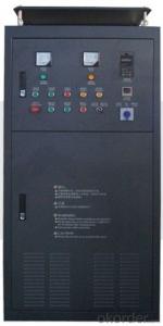
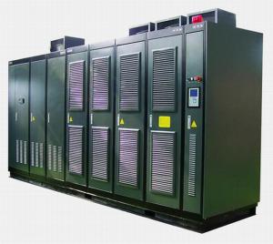
Installation type | Wall-mounted type, floor cabinet type | |
Cooling mode | Air-forced cooling | |
- Q: What is the difference between a frequency converter and a servo controller?
- Servo system: 1 servo drives in the premise of the development of frequency conversion technology, the current loop in the internal drive, speed loop and position loop (inverter without the ring) of algorithm operation and control technology is more accurate than the general frequency, but also in the function than the traditional servo many powerful, the main point can accurate position control. To control the speed and position of the pulse sequence controller sends the (of course there are also some integrated servo control unit or by bus communication way directly to set the parameters of position and velocity in the drive), drive the internal algorithm and faster and more accurate calculation and better performance of electronic devices to be more superior to converter. 2, motor servo motor of the material, structure and machining process is much higher than that of the AC motor drive inverter (general AC motor or constant torque, constant power and other types of motor), that is to say when the power driver output current and voltage and frequency change quickly, the servo motor can generate action response according to the change power changes, response and anti overload capacity is much higher than that of AC motor inverter drive motor, fundamental serious differences is two different performance. That is to say, not the inverter can not change the power supply signal, but the motor itself can not respond, so in the frequency of the internal algorithm settings, in order to protect the motor to do the corresponding overload settings. Of course, even if the output power of the inverter is not limited, some high-performance inverters can directly drive the servo motor!
- Q: What does the base frequency 60Hz represent in the inverter?
- How to set the frequency converter: inverter frequency parameter should be set to the rated frequency of the motor is set up, and not according to the load characteristic set, even if the selection is not suitable for motor load characteristics or parameters must also try to follow the motor, easy over-current or overload.
- Q: Where is the difference between soft starter and converter?
- Are two completely different uses of the product. The inverter is used for the need for speed place, its output voltage and frequency change not only change; the soft starter is actually a regulator for motor starting, output voltage and frequency change not only change. Inverters have all of the soft starter functions, but they cost much more than soft starters and have a much more complex structure.
- Q: What is the function of a frequency converter on an electric motor?
- Through the frequency converter, the motor can be adjusted speed, so as to obtain the speed required by itself, and also can reduce the motor running current and save energy and reduce consumption.
- Q: What does the RUN key on the inverter mean? How do you use it?
- According to the actual needs of the motor to provide the required power supply voltage, and then to achieve energy saving, speed control purposes, in addition, there are many inverter protection functions, such as over-current, overvoltage, overload protection, etc.. With the continuous improvement of the degree of industrial automation, inverter has also been widely used.
- Q: What's the role of an electric car, the part of a traditional car?
- Optimal energy utilization.The optimal utilization of energy is another basic requirement of electric vehicle, the control system can be as much as possible the use of energy, including the use of overheating and regenerative braking energy, make full use of limited energy. Ability feedback can implement this function. It includes two kinds of vehicle braking capability feedback and vehicle coasting ability feedback. In our state, the drive motor according to the operation of the generator, the vehicle kinetic energy into electricity, can play 3 roles: auxiliary braking; energy recovery to the power battery, thereby prolonging the vehicle mileage; in vehicle heating demand, can directly use this energy heating.
- Q: What is the difference between inverter energy consumption braking and motor energy consumption braking?
- Your question, I think it is the difference between regenerative braking and braking of the motor function for active inverter regenerative braking to use inverter feedback power, so there is the braking inverter of the argument?? First of all, define some of your concepts, the motor is divided into reverse braking, energy consumption braking, regenerative braking three. The energy consumption braking of the inverter is called the energy consumption braking by using the braking resistance in the DC loop to absorb the regenerative electric energy of the motor,The utility model has the advantages of simple structure; no pollution to the power grid (for comparison, action and feedback) low cost; the disadvantage is low efficiency, especially to consume a lot of energy and braking resistance will be in frequent braking capacity will increase.
- Q: 5.5KW frequency converter with 4.5KW deep water pump, pressure regulator by conveying signal to frequency converter start normal, the pressure to reduce the frequency converter after the start, to about 30Hz in order to maintain the pressure about shocks, 30 seconds inverter over-current alarm. Can it be the fault of the frequency converter? How should I check it?
- Once the inverter has hardware faults, such as rectifier, inverter circuit and so on. The IGBT module may be damaged, and most of the time it will damage the drive components. The most easily damaged devices are the regulator and the optocoupler. Conversely, components such as capacitance, leakage, breakdown, and optocoupler aging can also cause IGBT modules to burn out or frequency conversion, and output voltage is unbalanced. Check if there is a problem with the drive circuit, and compare the resistance of the trigger terminals when the circuit is not switched on. The voltage waveform at the trigger end can be measured when the power is switched on. However, some inverters are not equipped with modules and can not switch on, when the module P end of the series into a false load, to prevent detection, mistakenly touch the originator or other circuit burned module. In this case, the frequency converter has been seriously damaged (by measuring whether the input and output are short circuited), then there should be special technical personnel maintenance, and generally may not re energized, so as not to expand the scope of failure.
- Q: Is the voltage low? The younger brother is bored to death, no problem with the wire drawing machine, the full load will jump off. Display frequency converter overload and acceleration operation overcurrent. Help me please.
- There are only three reasons for the POFF fault: (1) the DC bus voltage detected by the machine is seriously low. (2) lack of phase signal. (3) the voltage level parameter of 220V machine is wrong. [method] use the shift key on the keyboard or the mask to switch the display content to the display bus voltage status.
- Q: I would like to ask vector control of the frequency converter, how the motor does not turn. What parameters are set up
- No PG vector control (motor with encoder), set the motor parameters self-learning, rated voltage, rated current, fundamental frequency (50, 33.3, 20 HZ motor should pay attention to what kind of), pole number, frequency speed, rated power, the maximum output frequency, etc., set the end after the rotation form self-learning (motor without load), or stop shape self-learning. Even the self-learning control model parameter to the external terminal control, analog voltage is changed to external control, can be CNC, PLC or PC to control its operation.
Send your message to us
Frequency Inverter 3 phase VFD VSD
- Ref Price:
-
- Loading Port:
- China Main Port
- Payment Terms:
- TT OR LC
- Min Order Qty:
- -
- Supply Capability:
- -
OKorder Service Pledge
OKorder Financial Service
Similar products
Hot products

Hot Searches
Related keywords

