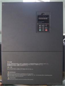

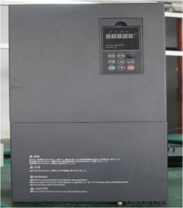
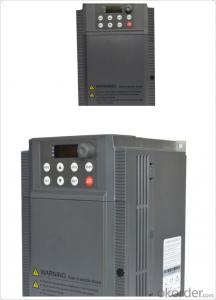
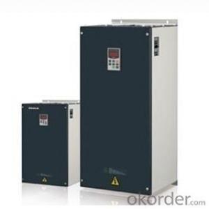
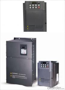
VFD Frequency Inverter 3 phase input 3 phase output 220V /380V
- Ref Price:
-

- Loading Port:
- China Main Port
- Payment Terms:
- TT OR LC
- Min Order Qty:
- -
- Supply Capability:
- -
OKorder Service Pledge
OKorder Financial Service
You Might Also Like


Specifications
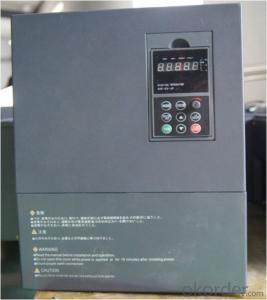
1.220V Single Phase Variable Frequency Drive 2.2KW
2.Advanced control technology
3.Easy to operate
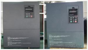
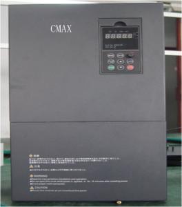
220V Single Phase Variable Frequency Drive 2.2KW
General
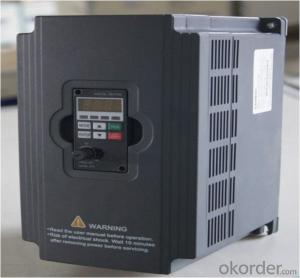
CNBM frequency inverter is a high-quality, multi-function,
low-noise variable frequency drive which is designed, developed and manufactured according to international standards.
It can meet different needs of industrial conditions.
The inverter applies advanced control technology of space voltage vector PWM, with functions of constant voltage control, power-off restart, dead zone compensation, automatic torque compensation, online modification parameter, high-speed impulse input, simple PLC and traverse.
Product Name:CMAX-VCG15/P18.5T3 ~ CMAX-VCG18.5/P22T3
Application
Textile: coarse spinner, spinning frame, wrap-knitting machine, loom, knitting machine, silk-spinning machine, etc.
Plastic: extruder, hauling machine, decorating machine, etc.
Pharmacy: mixer, roaster, etc.
Woodworking: engraving machine, sander, veneer peeling lathe, etc.
Papermaking: single type papermaking machine, etc.
Machine tool: non-core grinding machine, optical lens grinding machine, cutting mill, etc.
Printing: cloth-washing machine, dye vat, etc.
Cement: feeder, air blower, rotary furnace, mixer, crusher, etc
Fan and pump: kinds of fans, blowers and pumps
Specification
Item | Specification | |
Input | Input voltage | 220/380V±15% |
Input frequency | 47~63Hz | |
Output | Output voltage | 0~input voltage |
Output frequency | 0~600Hz | |
Peripheral interface characteristics | Programmable digital input | 4 switch input, 1 high-speed impulse input |
Programmable analog input | AI1: 0~10V input AI2: 0~10V input or 0~20mA input, | |
Programmable open collector output | 2 Output (3.7kW and above: 1 Open collector output) | |
Relay Output | 1 Output (3.7kW and above: 2 Relay output) | |
Analog output | 2 Output, one is 0~10V, another is 0~20mA or 0~10V | |
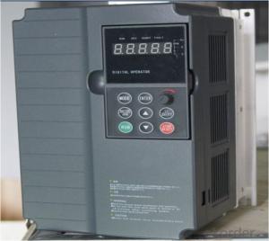
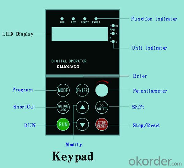
Keypad | Display:5-digit 8-section LED (Red), 2 indicators; parameter setting: 8 keys (including multi-function hot key ), 1 potentiometer | |
Technical performance characteristics | Control mode | All digital space voltage vector SVPWM algorism |
Overload capacity | G purpose: 150% rated current 60s P purpose: 120% rated current 60s | |
Speed ratio | 1: 100 | |
Carrier frequency | 1.0~10.0kHz | |
Torque compensation | Linear, multi-point, 1.3th power, 1.7th power, 2.0th power reduced torque; Compensation voltage range: automatic compensation and manual compensation 0.1~10% | |
Automatic voltage adjustment | It can automatically maintain output voltage constant when grid voltage fluctuates. | |
Automatic current adjustment | When the current is over current limit, under clocking automatically limits output current. | |
Function characteristics | Frequency setting mode | Keypad digital analog input, keypad potentiometer, impulse frequency, communication, multi-step speed and simple PLC, PID setting and so on, switch-over of setting modes. |
Simple PLC, multi-step speed control | 16-step speed control | |
Special function | Traverse control, length control, time control | |
QUICK/JOG key | User-defined multi-function hot key | |
Protection function | Over-current, Over voltage, under-voltage, over-heat, phase failure, over-load and motor over-load | |
Working condition | Installation site | Indoor, altitude of less than 1km, dust free, non-corrosive gases, no direct sunlight |
Application environment | -10°C~+40°C, 20~90%RH (no dew) | |
Vibration | Less than 0.5g | |
Storage temperature | -25°C~+65°C | |
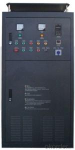
Installation type | Wall-mounted type, floor cabinet type | |
Cooling mode | Air-forced cooling | |
- Q: What does a frequency converter do?
- Mainly used to drive AC motors, AC motors to achieve stepless speed regulation.For example, for the fan, with frequency converter to adjust the speed of the motor speed, you can change the size of the air supply.There are many occasions that need speed regulation. Using frequency converter to speed up is simple and energy-saving.
- Q: How does the frequency converter fit the brake unit and the brake resistor?!
- When the motor drives the motor to stop, the load on the motor is kinetic, and the motor must be consumed to stop the motor
- Q: The frequency converter is in use suddenly the speed reduces, then the debugging is out of control, how to do?
- Excessive voltage generation and regenerative braking, the so-called inverter over-voltage, refers to a variety of reasons caused by inverter voltage exceeds the rated voltage, concentrated in the DC bus frequency converter DC voltage. In normal operation, the DC part voltage of converter is the average value after three-phase full wave rectification.
- Q: Can the frequency converter 7.5KW take the motor with 11KW?
- The inverter rated current 7.5 kW is about 17A, the constant current 11KW converter is about 25A 11KW Oh, no-load current is about 8A, 17A is greater than 8A, so the 7.5KW motor with 11KW is no problem, but you have much load, full of motor current 11KW is 25A, 7.5KW certainly do not move with the! That is to say, you can carry 11KW motors running under light loads. Don't worry, the frequency converter will burn down, because the inverter has overload and over-current protection, it can protect your inverter and your motor from damage!
- Q: What does the base frequency 60Hz represent in the inverter?
- For example: if the rated frequency of the motor is 20HZ, the fundamental frequency should be set to 20HZ; if the rated frequency of the motor is 33.3HZ, the fundamental frequency should be set to 33.3HZ; if the rated frequency of the motor is 50HZ, the fundamental frequency should be set to 50HZ; if the rated frequency of the motor is 60HZ, the fundamental frequency should be set to 60HZ; if the rated the working frequency of the motor is 100HZ, the fundamental frequency should be set to 100HZ.
- Q: How does the PLC process the inverter output signal?
- 1. The analog signals of the converter (such as the 4~20mA signal) are received in the analog input module of the PLC (for example, the EM235 module)2, the input signal processing (32000 digital quantity into 50HZ frequency signal)3. Compare the resulting frequency signals with their own internal settings
- Q: Why does the frequency change when the frequency converter regulates the frequency?
- Because the product of three-phase asynchronous motor stator phase voltage and frequency and flux is proportional to the frequency when the downward adjustment, if the sustain voltage is constant, the flux must be increased, this will cause the main magnetic saturation excitation current passing, the surge in motor damage.As a result, the voltage is usually adjusted down proportionally as the frequency is lowered down.However, when adjusting the frequency, the voltage is not adjustable in order to avoid the excessive voltage damage of the motor. Therefore, in the use of frequency converter overclocking motor, the magnetic flux will decline, the motor output torque characteristics will move to the left.
- Q: How to deal with the fault Yaskawa inverter GF
- See the Yaskawa inverter protection circuit structure, and the other is the same frequency. Over current OL1, OL2 and OL3 fault signals should be current transformers and subsequent current detection and processing circuits and CPUThe fault signals of GF (ground) and OC (load side short circuit) shall be fed directly to the protection circuit of the drive circuit board to feed the CPU. The difference is that at the initial stage of the start-up, the detection module is abnormal, i.e., a fault is reported.If the module is detected in operation, the OC fault is reported. These two kinds of signals, but also revealed such a message: the initial stage, it has not yet established the three-phase output voltage, the load is not running, the actual fault sources should be inverter driving circuit or the IGBT module itself caused by the abnormal, but does not rule out a ground fault load;In operation, there is a very large current, jump OC, the load side of the probability of failure is large, but also over current fault, rather than ground fault. The difference between GF and OC faults and what they mean is really reasonable.
- Q: 5.5KW frequency converter with 4.5KW deep water pump, pressure regulator by conveying signal to frequency converter start normal, the pressure to reduce the frequency converter after the start, to about 30Hz in order to maintain the pressure about shocks, 30 seconds inverter over-current alarm. Can it be the fault of the frequency converter? How should I check it?
- UndervoltageThere is a problem with the power input circuit. It may be caused by serious overloading of the line or bad contact with the line. The letter "E" PMU display panel LCD screen SIEMENS 6SE70 series inverter, the inverter can not work, press the P button and to stop transmission are invalid, check the operation manual and the related introduction, in the external DC24V power supply, that is low voltage, solution, inverter working.
- Q: What role does input and output reactor play?
- Enter the reactor to suppress the surge voltage and surge current protection, frequency converter, and prolong its service life and prevent the harmonic interference, at the same time as the speed control inverter adopts frequency conversion mode, so often produce harmonics and waveform distortion in the speed, will affect the normal use of equipment, therefore, should be installed in a line choke the input end of the inverter can improve the power factor and harmonic current suppression filter, harmonic voltage and harmonic current, improve the quality of power grid.
Send your message to us
VFD Frequency Inverter 3 phase input 3 phase output 220V /380V
- Ref Price:
-
- Loading Port:
- China Main Port
- Payment Terms:
- TT OR LC
- Min Order Qty:
- -
- Supply Capability:
- -
OKorder Service Pledge
OKorder Financial Service
Similar products
Hot products

Hot Searches
Related keywords

