
China Best Selling VFD Frequency Drive 3 phase 380V 11kw
- Ref Price:
-

- Loading Port:
- Tianjin
- Payment Terms:
- TT OR LC
- Min Order Qty:
- 1 pc
- Supply Capability:
- 100000 pc/month
OKorder Service Pledge
OKorder Financial Service
You Might Also Like


Application
Textile: coarse spinner, spinning frame, wrap-knitting machine, loom, knitting machine, silk-spinning machine, etc.
Plastic: extruder, hauling machine, decorating machine, etc.
Pharmacy: mixer, roaster, etc.
Woodworking: engraving machine, sander, veneer peeling lathe, etc.
Papermaking: single type papermaking machine, etc.
Machine tool: non-core grinding machine, optical lens grinding machine, cutting mill, etc.
Printing: cloth-washing machine, dye vat, etc.
Cement: feeder, air blower, rotary furnace, mixer, crusher, etc
Fan and pump: kinds of fans, blowers and pumps
General
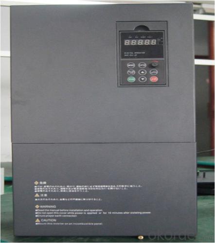
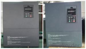
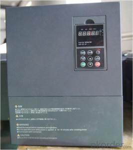
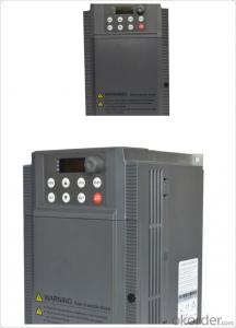
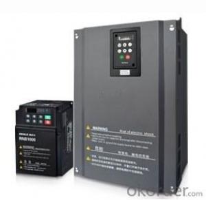
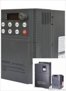
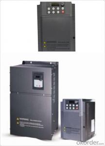
CNBM frequency inverter is a high-quality, multi-function,
low-noise variable frequency drive which is designed, developed and manufactured according to international standards.
It can meet different needs of industrial conditions.
The inverter applies advanced control technology of space voltage vector PWM, with functions of constant voltage control, power-off restart, dead zone compensation, automatic torque compensation, online modification parameter, high-speed impulse input, simple PLC and traverse.
Specification
Item | Specification | |
Input | Input voltage | 220/380V±15% |
Input frequency | 47~63Hz | |
Output | Output voltage | 0~input voltage |
Output frequency | 0~600Hz | |
Peripheral interface characteristics | Programmable digital input | 4 switch input, 1 high-speed impulse input |
Programmable analog input | AI1: 0~10V input AI2: 0~10V input or 0~20mA input, | |
Programmable open collector output | 2 Output (3.7kW and above: 1 Open collector output) | |
Relay Output | 1 Output (3.7kW and above: 2 Relay output) | |
Analog output | 2 Output, one is 0~10V, another is 0~20mA or 0~10V | |
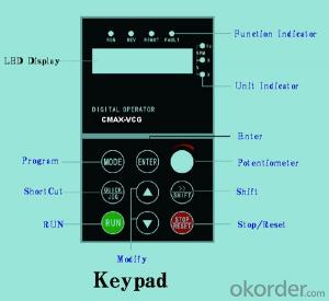
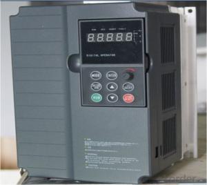
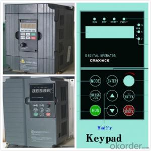
Keypad | Display:5-digit 8-section LED (Red), 2 indicators; parameter setting: 8 keys (including multi-function hot key ), 1 potentiometer | |
Technical performance characteristics | Control mode | All digital space voltage vector SVPWM algorism |
Overload capacity | G purpose: 150% rated current 60s P purpose: 120% rated current 60s | |
Speed ratio | 1: 100 | |
Carrier frequency | 1.0~10.0kHz | |
Torque compensation | Linear, multi-point, 1.3th power, 1.7th power, 2.0th power reduced torque; Compensation voltage range: automatic compensation and manual compensation 0.1~10% | |
Automatic voltage adjustment | It can automatically maintain output voltage constant when grid voltage fluctuates. | |
Automatic current adjustment | When the current is over current limit, under clocking automatically limits output current. | |
Function characteristics | Frequency setting mode | Keypad digital analog input, keypad potentiometer, impulse frequency, communication, multi-step speed and simple PLC, PID setting and so on, switch-over of setting modes. |
Simple PLC, multi-step speed control | 16-step speed control | |
Special function | Traverse control, length control, time control | |
QUICK/JOG key | User-defined multi-function hot key | |
Protection function | Over-current, Over voltage, under-voltage, over-heat, phase failure, over-load and motor over-load | |
Working condition | Installation site | Indoor, altitude of less than 1km, dust free, non-corrosive gases, no direct sunlight |
Application environment | -10°C~+40°C, 20~90%RH (no dew) | |
Vibration | Less than 0.5g | |
Storage temperature | -25°C~+65°C | |
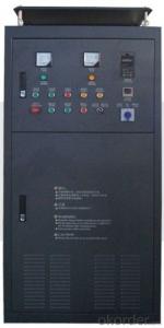
Installation type | Wall-mounted type, floor cabinet type | |
Cooling mode | Air-forced cooling | |
- Q: Why does the frequency converter cause interference?
- Isolation of interference: the so-called interference isolation is the separation of the source of interference from the susceptible part from the circuit so that they do not generate electrical contact. Usually in the power supply and controller and transmitter amplifier circuit, in the power line using isolation transformer, so as to avoid conduction interference, power isolation transformer can use noise isolation transformer.
- Q: It was when processing a workpiece, processing spindle stops suddenly (other are normal) a check is, I jump out of the inverter, I can click on a processing, and then processing not long after they happen, (do not open the machine spindle machining will also be the case)
- Suggest you in the inverter power installed a frequency converter input filter, try it, feel a bit like electromagnetic interference caused by frequency converter mistakenly stop ah.
- Q: Today, I was asked the question, and I also brought it to you to share the following Oh!
- The inverter (power converter, Power Inverter) is a kind of DC12V can be converted to DC and AC220V AC power the same, for general use of electrical appliances, power converter with a convenient car.
- Q: Ask, what is the ratio of frequency converter?
- Three inverter operation indicator light, the output frequency from 0.0Hz to potentiometer set frequency and the output frequency ratio is 1:1.5:2, adjust the tone potentiometer, change the motor speed and the speed of three units, according to the proportion of linkage. The output frequency of the three inverters can be adjusted with three Trimming Potentiometer respectively.
- Q: How much is the motor 90KW and the frequency converter selected?Colleagues suggest 110W?The cost will be higherIs it okay to choose 90KW?
- You refer to the type and parameters of the frequency changer to select.
- Q: The difference between soft starter and converter
- The soft starter is during the start-up of the equipment to take blood pressure or other ways to reduce the starting current of the inverter machine, the device is in operation according to the equipment load by changing the size of the power frequency and regulating equipment output.
- Q: What is the difference between inverter energy consumption braking and motor energy consumption braking?
- A direct current is generated in the stator winding so that a fixed magnetic field is generated. At this point, the rotor cuts the magnetic field lines in the direction of rotation, resulting in a braking torque. Because the braking method is not like regenerative braking (using frequency converter), the energy generated by braking is fed back to the grid, but the energy is dissipated by the motor alone, so it is called energy consumption braking. The utility model is also used for braking by direct current in the stator winding, so the energy consumption braking is called DC injection braking. By using the backward switch Q to return the point voltage back to the grid, the armature current will become a copy, and the current will be of the same magnitude, resulting in a great braking torque of the motor, which will stop the motor.
- Q: How do you set the frequency with panels?. What are the specific steps?
- Frequency converter is the application of frequency conversion technology and micro electronics technology, by changing the power supply frequency of the motor to control AC motor power control equipment. The frequency converter is mainly composed of rectifier (AC DC converter), filter, inverter (DC AC converter), brake unit, drive unit, detection unit, micro processing unit and so on. Inverter by internal IGBT drive voltage and frequency off to adjust the output power, the power supply voltage required to provide according to the actual needs of the motor, so as to achieve the purpose of speed, energy saving, in addition, there are a lot of protection drive, such as over-current, over-voltage, overload protection and so on. With the continuous improvement of the degree of industrial automation, inverter has also been widely used.
- Q: I would like to ask vector control of the frequency converter, how the motor does not turn. What parameters are set up
- Because the dynamic mathematical model of induction motor is a high order, nonlinear and strong coupling multivariable system. In the 70s of last century, SIEMENS Engineer F.Blaschke first proposed asynchronous motor vector control theory to solve the AC motor torque control problem. The basic principle of vector control is achieved through the measurement and control of induction motor stator current vector, according to the principle of field orientation respectively, excitation current and torque current of induction motor control, so as to achieve the purpose of controlling the torque of asynchronous motor. In particular the stator current vector is decomposed into a component of current magnetic field (excitation current) and the torque producing current component (torque) to control respectively, and at the same time to control the amplitude and phase of the two components, namely the control of stator current vector, so that this control method is called vector control mode. In brief, the vector control is to decouple the magnetic flux and the torque, which is beneficial to design the regulator of both of them, so as to realize the high speed control of the AC motor. There are vector control methods based on slip frequency control, speed sensorless vector control method and vector control method with speed sensor. Thus, a three-phase induction motor can be equivalent to a DC motor to control, so as to obtain the same static and dynamic performance as the DC speed regulating system. Vector control algorithm has been widely used in Siemens, AB, GE, Fuji and other international large company frequency converter.
- Q: What is the main harmonic produced by a transducer? How about the degree?
- To reduce the influence of harmonics, various measures can be taken, but for the inverter, the main circuit is to install an AC reactor.The input side of the inverter generates the harmonic mechanism: for the inverter, as long as there is a rectifier circuit on the power supply side, it will produce harmonics caused by nonlinearity. Based on the three-phase bridge rectifier circuit for example, AC grid voltage for a sine wave, square wave AC input current waveform, the waveform, according to Fourier series can be decomposed into fundamental and harmonics, usually containing 6m + 1 (m=1,2) harmonics, the harmonics in power grid. A single fundamental wave, combined with several harmonic waves, is called an abnormal wave
Send your message to us
China Best Selling VFD Frequency Drive 3 phase 380V 11kw
- Ref Price:
-
- Loading Port:
- Tianjin
- Payment Terms:
- TT OR LC
- Min Order Qty:
- 1 pc
- Supply Capability:
- 100000 pc/month
OKorder Service Pledge
OKorder Financial Service
Similar products
Hot products

Hot Searches
Related keywords

