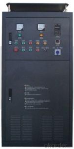
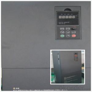
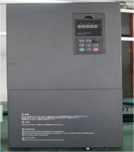
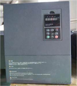
China best selling VFD Frequency Drive 3 phase 380V 55KW
- Ref Price:
-

- Loading Port:
- Tianjin
- Payment Terms:
- TT OR LC
- Min Order Qty:
- 1 pc
- Supply Capability:
- 100000 pc/month
OKorder Service Pledge
OKorder Financial Service
You Might Also Like


Specifications
1.220V Single Phase Variable Frequency Drive 2.2KW
2.Advanced control technology
3.Easy to operate
220V Single Phase Variable Frequency Drive 2.2KW
General
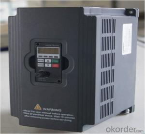
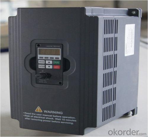
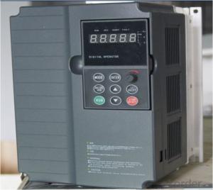
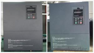
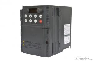
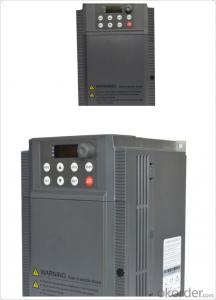
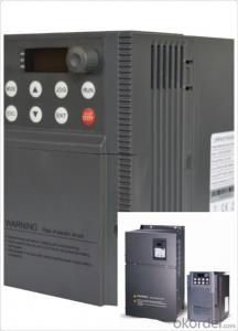
CNBM frequency inverter is a high-quality, multi-function,
low-noise variable frequency drive which is designed, developed and manufactured according to international standards.
It can meet different needs of industrial conditions.
The inverter applies advanced control technology of space voltage vector PWM, with functions of constant voltage control, power-off restart, dead zone compensation, automatic torque compensation, online modification parameter, high-speed impulse input, simple PLC and traverse.

Product Name:CMAX-VCG15/P18.5T3 ~ CMAX-VCG18.5/P22T3
Application
Textile: coarse spinner, spinning frame, wrap-knitting machine, loom, knitting machine, silk-spinning machine, etc.
Plastic: extruder, hauling machine, decorating machine, etc.
Pharmacy: mixer, roaster, etc.
Woodworking: engraving machine, sander, veneer peeling lathe, etc.
Papermaking: single type papermaking machine, etc.
Machine tool: non-core grinding machine, optical lens grinding machine, cutting mill, etc.
Printing: cloth-washing machine, dye vat, etc.
Cement: feeder, air blower, rotary furnace, mixer, crusher, etc
Fan and pump: kinds of fans, blowers and pumps
Specification
Item | Specification | |
Input | Input voltage | 220/380V±15% |
Input frequency | 47~63Hz | |
Output | Output voltage | 0~input voltage |
Output frequency | 0~600Hz | |
Peripheral interface characteristics | Programmable digital input | 4 switch input, 1 high-speed impulse input |
Programmable analog input | AI1: 0~10V input AI2: 0~10V input or 0~20mA input, | |
Programmable open collector output | 2 Output (3.7kW and above: 1 Open collector output) | |
Relay Output | 1 Output (3.7kW and above: 2 Relay output) | |
Analog output | 2 Output, one is 0~10V, another is 0~20mA or 0~10V | |
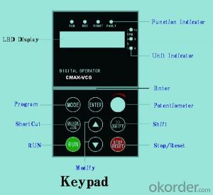
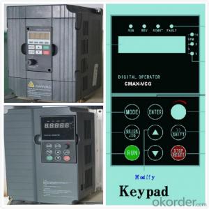
Keypad | Display:5-digit 8-section LED (Red), 2 indicators; parameter setting: 8 keys (including multi-function hot key ), 1 potentiometer | |
Technical performance characteristics | Control mode | All digital space voltage vector SVPWM algorism |
Overload capacity | G purpose: 150% rated current 60s P purpose: 120% rated current 60s | |
Speed ratio | 1: 100 | |
Carrier frequency | 1.0~10.0kHz | |
Torque compensation | Linear, multi-point, 1.3th power, 1.7th power, 2.0th power reduced torque; Compensation voltage range: automatic compensation and manual compensation 0.1~10% | |
Automatic voltage adjustment | It can automatically maintain output voltage constant when grid voltage fluctuates. | |
Automatic current adjustment | When the current is over current limit, under clocking automatically limits output current. | |
Function characteristics | Frequency setting mode | Keypad digital analog input, keypad potentiometer, impulse frequency, communication, multi-step speed and simple PLC, PID setting and so on, switch-over of setting modes. |
Simple PLC, multi-step speed control | 16-step speed control | |
Special function | Traverse control, length control, time control | |
QUICK/JOG key | User-defined multi-function hot key | |
Protection function | Over-current, Over voltage, under-voltage, over-heat, phase failure, over-load and motor over-load | |
Working condition | Installation site | Indoor, altitude of less than 1km, dust free, non-corrosive gases, no direct sunlight |
Application environment | -10°C~+40°C, 20~90%RH (no dew) | |
Vibration | Less than 0.5g | |
Storage temperature | -25°C~+65°C | |
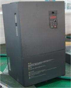
Installation type | Wall-mounted type, floor cabinet type | |
Cooling mode | Air-forced cooling | |
- Q: What are the modes of operation of a frequency converter?
- Frequency converter with motor no-load operation, 11 set motor power and pole number, to consider the work current of the converter. 21 set the maximum output frequency, frequency and torque characteristics of the inverter. VPf types include items such as maximum frequency, basic frequency and torque type. The highest frequency is the highest frequency that the inverter motor system can operate, because the highest frequency of the inverter itself may be higher, when the highest frequency allowed by the motor is lower than the frequency conversion
- Q: Surface grinder can add frequency converter, what are the advantages and disadvantages?
- Three frequency converter successfully used in NC machine toolsIn recent years, with the rapid development of the economy, the machine tool industry has also made rapid progress: it is reflected in the wide application of new technology and the obvious improvement of enterprise benefit. At present, the mainstream of consumption in machine tool industry is CNC machine tools. From the domestic and international market demand for CNC machine tools, after the NC machine tool market has the following characteristics: first, the economic CNC machine tools is the mainstream of the future products. Two, using new technology to reduce costs and improve product stability is the key to enterprise survival. Below we in the machine tool drive aspect uses the frequency control speed to say SAJ frequency changer in this profession application situation:
- Q: What does 0L1 stand for?
- The acceleration is generally overloaded during acceleration. Load inertia is too large, the inverter power is small, or the acceleration time is too short, and so on
- Q: Knowledge, principle and operation method of frequency converter.
- Sinusoidal pulse width modulation (SPWM) of U/f=C with frequency converter control mode:The characteristics of SPWM inverter control way is to control the circuit has simple structure and low cost, the mechanical properties of hardness is also good, can meet the general requirements of smooth speed transmission, has been widely used in various fields of industry. However, when the output voltage is low, the torque is significantly affected by the stator resistance pressure drop, so that the maximum output torque is reduced. In addition, the mechanical characteristics of DC motor can not hard, dynamic torque capacity and static performance is not satisfactory, and the system performance is not high, the control curve will change with the change of the load torque and motor torque, slow response, low utilization rate is not high, due to the stator resistance and the existence of dead time effect of the inverter performance the poor stability, etc.. Therefore, people have studied vector control frequency conversion speed regulation.
- Q: The functions of frequency converter and UPS are similar, especially the power frequency UPS?
- The obvious difference between the two:1, the former output amplitude and frequency adjustable, the latter output is a single fixed amplitude, frequency;2, the former does not use batteries, and the latter requires batteries.
- Q: What are the parameters of the frequency converter? Thank you
- That is to say, the upper and lower amplitudes of the output frequency of the inverter. Frequency * * is to prevent misoperation or external frequency set signal source failure, resulting in the output frequency is too high or too low, in order to prevent damage to a device protection function. In the application, according to the actual situation can be set. This function can also be used as a speed limit, if the conveyor belt, the conveying material is not too much, to reduce the mechanical and wear belts, be driven by inverter, and the inverter upper frequency settings for a particular frequency, so it can make the belt conveyor running on a fixed low speed work
- Q: How can I control the frequency converter with a computer?
- The commonly used PLC and DCS control system in industrial area are applicable to the conditions of inverter interface control module, can realize the closed-loop converter convenient automatic control in the control system, widely used in large and medium. The control device for some smallexperimental device and embedded processor in inverter control, generally also need to deal with the keyboard input, display, data acquisition and other work such as process control, this control is more suitable for single-chip control system as the core, and uses PLC and operation panel, it can achieve the function but the cost is too high. Should not be used.
- Q: What's the difference between universal inverter and fan pump converter?
- Fan and pump load:In a variety of fans, pumps, oil pumps, with the rotation of the impeller, the air or liquid within a certain speed range of resistance is roughly proportional to the speed of the 2 side of the n. As the speed decreases, the torque decreases by 2 times the speed. The power required for this kind of load is proportional to the 3 power of the velocity. When the required air volume and flow rate are reduced, the frequency and speed of air flow can be regulated by the frequency converter, so the energy can be saved substantially. Because the power required at high speed increases with the speed, and is proportional to the speed of the three side, so the fan and pump load should not be used in the ultra power frequency operation
- Q: Frequency converter OC alarm, what's the matter?
- A "Taiwan" type N2 power type, power jump UL or UU fault, refused operation. Check the three-phase current transformer signal, the three signal is seriously deviation, or at least it has broken two. But check the specification of the manual code, there is no such twoKind of fault code, guess this code is factory repair personnel can crack password, insufficient for outside humanitarian. Does it also indirectly indicate the OC fault? Only to be repaired in order to have an answer.
- Q: Delta inverter fault output which parameter is set?
- Overload overload fault include frequency overload and overload. The electric machine may be accelerated in short time, the DC brake is too large, the grid voltage is too low, the heavy load causes. Usually by extending the acceleration time and prolong the braking time, check the power voltage. The heavy load, the motor and inverter can not drag this may be due to mechanical load, lubrication is not good. The former must replace high power motor and inverter; if the latter want to overhaul production machinery.
Send your message to us
China best selling VFD Frequency Drive 3 phase 380V 55KW
- Ref Price:
-
- Loading Port:
- Tianjin
- Payment Terms:
- TT OR LC
- Min Order Qty:
- 1 pc
- Supply Capability:
- 100000 pc/month
OKorder Service Pledge
OKorder Financial Service
Similar products
Hot products

Hot Searches
Related keywords

