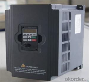
China VFD Frequency Drive 3 phase 220V 380V
- Ref Price:
-

- Loading Port:
- Tianjin
- Payment Terms:
- TT OR LC
- Min Order Qty:
- 1 pc
- Supply Capability:
- 100000 pc/month
OKorder Service Pledge
OKorder Financial Service
You Might Also Like

General
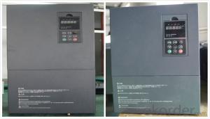
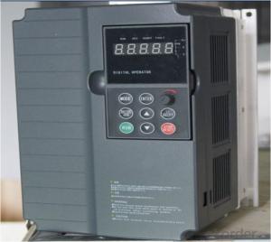
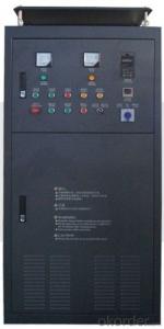
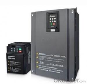
CNBM frequency inverter is a high-quality, multi-function,
low-noise variable frequency drive which is designed, developed and manufactured according to international standards.
It can meet different needs of industrial conditions.
The inverter applies advanced control technology of space voltage vector PWM, with functions of constant voltage control, power-off restart, dead zone compensation, automatic torque compensation, online modification parameter, high-speed impulse input, simple PLC and traverse.
Application
Textile: coarse spinner, spinning frame, wrap-knitting machine, loom, knitting machine, silk-spinning machine, etc.
Plastic: extruder, hauling machine, decorating machine, etc.
Pharmacy: mixer, roaster, etc.
Woodworking: engraving machine, sander, veneer peeling lathe, etc.
Papermaking: single type papermaking machine, etc.
Machine tool: non-core grinding machine, optical lens grinding machine, cutting mill, etc.
Printing: cloth-washing machine, dye vat, etc.
Cement: feeder, air blower, rotary furnace, mixer, crusher, etc
Fan and pump: kinds of fans, blowers and pumps
Specification
Item | Specification | |
Input | Input voltage | 220/380V±15% |
Input frequency | 47~63Hz | |
Output | Output voltage | 0~input voltage |
Output frequency | 0~600Hz | |
Peripheral interface characteristics | Programmable digital input | 4 switch input, 1 high-speed impulse input |
Programmable analog input | AI1: 0~10V input AI2: 0~10V input or 0~20mA input, | |
Programmable open collector output | 2 Output (3.7kW and above: 1 Open collector output) | |
Relay Output | 1 Output (3.7kW and above: 2 Relay output) | |
Analog output | 2 Output, one is 0~10V, another is 0~20mA or 0~10V | |
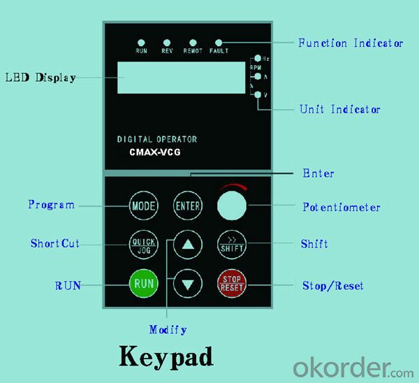
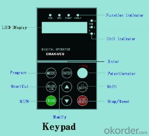
Keypad | Display:5-digit 8-section LED (Red), 2 indicators; parameter setting: 8 keys (including multi-function hot key ), 1 potentiometer | |
Technical performance characteristics | Control mode | All digital space voltage vector SVPWM algorism |
Overload capacity | G purpose: 150% rated current 60s P purpose: 120% rated current 60s | |
Speed ratio | 1: 100 | |
Carrier frequency | 1.0~10.0kHz | |
Torque compensation | Linear, multi-point, 1.3th power, 1.7th power, 2.0th power reduced torque; Compensation voltage range: automatic compensation and manual compensation 0.1~10% | |
Automatic voltage adjustment | It can automatically maintain output voltage constant when grid voltage fluctuates. | |
Automatic current adjustment | When the current is over current limit, under clocking automatically limits output current. | |
Function characteristics | Frequency setting mode | Keypad digital analog input, keypad potentiometer, impulse frequency, communication, multi-step speed and simple PLC, PID setting and so on, switch-over of setting modes. |
Simple PLC, multi-step speed control | 16-step speed control | |
Special function | Traverse control, length control, time control | |
QUICK/JOG key | User-defined multi-function hot key | |
Protection function | Over-current, Over voltage, under-voltage, over-heat, phase failure, over-load and motor over-load | |
Working condition | Installation site | Indoor, altitude of less than 1km, dust free, non-corrosive gases, no direct sunlight |
Application environment | -10°C~+40°C, 20~90%RH (no dew) | |
Vibration | Less than 0.5g | |
Storage temperature | -25°C~+65°C | |
Installation type | Wall-mounted type, floor cabinet type | |
Cooling mode | Air-forced cooling | |
- Q:That is, some parameters of the inverter, such as torque, current, frequency, etc., are displayed on the Kingview software interface, but not through the PLC. The idea that the MODBUS protocol between SIEMENS and 200PLC has never been successful before, so that's the idea of the ABB. If it can be achieved,Is it necessary to write the script program on the Kingview, and what problems should I pay attention to when using the MODBUS protocol in Kingview software?The problem is a little bit more, I hope the experts teach me this rookie! Thank you
- 1, requires two communications. The PLC and the Kingview use a communication port individually, and the PLC and the inverter use a communication port alone. 2, Kingview and PLC communication time, Kingview is the master station, PLC is from the station; and PLC and converter communication, PLC is the master station, frequency converter is from the station. 3, frequency converter control, do not use communication, use digital point output and analog output. 4, PLC and inverter as the slave station using Kingview configuration; Wang put the data to the PLC, let PLC run the program, go to the PLC of the configuration parameters of the inverter control read out, and then sent directly from the Kingview converter.
- Q:Today, I was asked the question, and I also brought it to you to share the following Oh!
- The frequency converter is the electric energy control device that transforms the power frequency power to another frequency by the on-off function of the power semiconductor device. We now use the converter mainly adopts the AC-DC-AC mode (VVVF inverter or variable frequency vector control), the first AC power into DC power supply through the rectifier, then the AC power into DC power supply frequency and voltage can be controlled by the supply of electric motive. The frequency converter circuit is usually composed of rectifier, intermediate DC link, inverter and control of 4 parts. The rectifier is a three-phase bridge controlled rectifier, and the inverter is IGBT three-phase bridge inverter, and the output is PWM waveform. The intermediate DC link is filter, DC energy storage and buffer reactive power.
- Q:What is the main harmonic produced by a transducer? How about the degree?
- Indirect frequency conversion has three different structure forms: (1) using controllable rectifier to change voltage, frequency conversion with inverter, voltage regulation and frequency modulation are carried out in two aspects respectively, and the two should coordinate with each other in control circuit. (2) with uncontrolled rectifier rectifier chopper inverter transformer, inverter, filter the inverter rectifier, voltage with pulse width (3) with uncontrolled rectifier rectifier, PWM inverter and inverter, this inverter device fully controlled only by controlled shutdown (such as IGBT) can output waveform is very realistic sine wave.
- Q:How does the frequency converter fit the brake unit and the brake resistor?!
- The kinetic energy of the motor shaft are much different. The load on the motor shaft, the kinetic energy is different, for example, motor used in cranes, in addition to the kinetic energy, potential energy and objects, should add up to the shaft of the motor, the energy will be consumed in the resistance.
- Q:What do you mean by the capacity of the inverter and the capacity of the motor?
- Because the motor consumes active power and consumes reactive power, and the reactive power is also occupied, the motor with 70KW can only be usedThe power is known to everyone
- Q:How to deal with the fault Yaskawa inverter GF
- This problem most likely. While G7 or F7 are generally Holzer Holzer sensor, sensor due to temperature. The influence of environmental factors such as humidity, work is easy to drift, to report "GF", another reason may be: E2-01 improper setting may also reported GF fault.
- Q:Knowledge, principle and operation method of frequency converter.
- Sinusoidal pulse width modulation (SPWM) of U/f=C with frequency converter control mode:The characteristics of SPWM inverter control way is to control the circuit has simple structure and low cost, the mechanical properties of hardness is also good, can meet the general requirements of smooth speed transmission, has been widely used in various fields of industry. However, when the output voltage is low, the torque is significantly affected by the stator resistance pressure drop, so that the maximum output torque is reduced. In addition, the mechanical characteristics of DC motor can not hard, dynamic torque capacity and static performance is not satisfactory, and the system performance is not high, the control curve will change with the change of the load torque and motor torque, slow response, low utilization rate is not high, due to the stator resistance and the existence of dead time effect of the inverter performance the poor stability, etc.. Therefore, people have studied vector control frequency conversion speed regulation.
- Q:How much is the motor 90KW and the frequency converter selected?Colleagues suggest 110W?The cost will be higherIs it okay to choose 90KW?
- You refer to the type and parameters of the frequency changer to select.
- Q:How do you understand the ramp up (descent) time of the inverter? Thank you!
- The ramp up time is to start from the 0 speed, inverter, running to reach the given speed (for example: 1420) the time required, in general, the longer the time, the frequency converter and motor impact is small. In the actual work process, according to process requirements to set the length of time. (more than 10-15 seconds) or so, if it is a pump or fan motor, do not need to change its rise time, the default can.
- Q:What is a frequency converter?
- Frequency conversion technology is born with the need of AC motor stepless speed regulation. After 1960s, the power electronic devices through SCR (SCR), GTO (gate turn off thyristor (BJT), bipolar power transistor), MOSFET (metal oxide semiconductor field effect transistor), SIT (static induction transistor), SITH (static induction thyristor (MGT), MOS control MCT (MOS) transistor, thyristor controlled), IGBT (insulated gate bipolar transistor), HVIGBT (high voltage insulated gate bipolar transistor) device to update the development process, to promote the continuous development of power electronics technology. The beginning of 1970s, PWM VVVF (PWMVVVF) control has aroused great attention. In 1980s, PWM mode optimization, as the core of frequency conversion technology, attracted people's interest and obtained many optimization models, among which the saddle wave PWM model was the best. Since the latter half of the 1980s, the VVVF inverters in developed countries such as the United States, Japan, Germany, Britain and other developed countries have already been put into the market and have been widely used.
1. Manufacturer Overview |
|
|---|---|
| Location | |
| Year Established | |
| Annual Output Value | |
| Main Markets | |
| Company Certifications | |
2. Manufacturer Certificates |
|
|---|---|
| a) Certification Name | |
| Range | |
| Reference | |
| Validity Period | |
3. Manufacturer Capability |
|
|---|---|
| a)Trade Capacity | |
| Nearest Port | |
| Export Percentage | |
| No.of Employees in Trade Department | |
| Language Spoken: | |
| b)Factory Information | |
| Factory Size: | |
| No. of Production Lines | |
| Contract Manufacturing | |
| Product Price Range | |
Send your message to us
China VFD Frequency Drive 3 phase 220V 380V
- Ref Price:
-
- Loading Port:
- Tianjin
- Payment Terms:
- TT OR LC
- Min Order Qty:
- 1 pc
- Supply Capability:
- 100000 pc/month
OKorder Service Pledge
OKorder Financial Service
Similar products
New products
Hot products

Hot Searches

