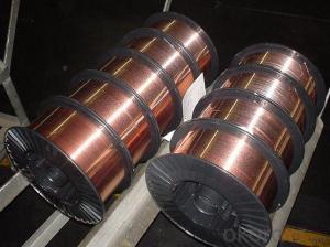

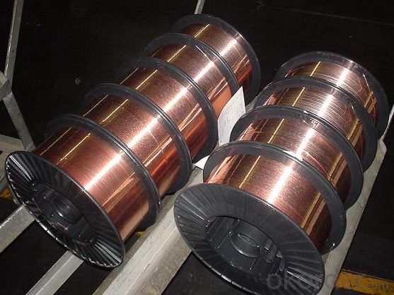
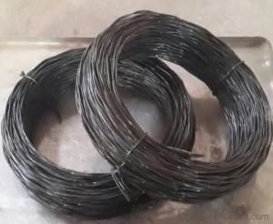
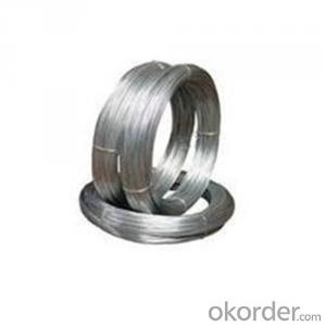
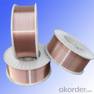
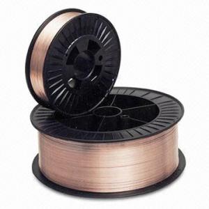
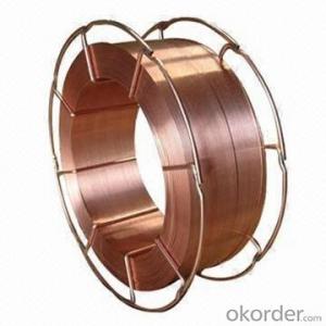
Widely use best priceER70S-6 CO2 welding wire
- Ref Price:
-

- Loading Port:
- Tianjin
- Payment Terms:
- TT OR LC
- Min Order Qty:
- 100 m.t.
- Supply Capability:
- 100000 m.t./month
OKorder Service Pledge
OKorder Financial Service
You Might Also Like


Quick Details
Place of Origin: Jiangsu, China (Mainland)
Model Number: ER70S-6
Material: Copper / Copper Alloy
Diameter: 0.6,0.8,0.9,1.0,1.2,1.6
Melting Point: 100
Weight: 1kg.5kg,15kg,20kg
Application: used to weld low carbon steel and low alloyed steel structure
Flux Content: Ar+CO2,CO2
Certificates: LR, DB,CWB, TUV, CE, ABS,BV,
QMS: ISO9001,ISO14000
Packaging & Delivery
| Packaging Details: | Packing:precision layer wound on plastic spool, each spool in a box, then boxes on wooden pallet, 72 box on one pallets. |
|---|---|
| Delivery Detail: | Within 20 days after confirmed order |
Specifications
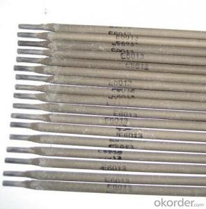
ER70S-6 wire
1.Size: 0.8mm-1.6mm
2.Certificate:ISO9001,TUV,DB,CE,ABS,LR ,CWB,BV
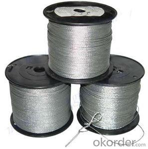
3.Spool packing
Model : AWS A5.18 ER70S-6
Place of Origin: China(Mainland)
Brand Name: Da Yunhe
1) Sizes: 0.6 - 1.6mm
2) Applications: shipbuilding, bridge building, machinery manufacture and general welding purposes
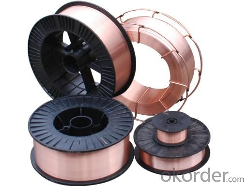
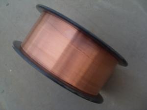
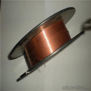
3) Packing:
Inner packing: 1kg,5kg,15kg,20kg/spool, precision layer wire in spool(plastic or metal spool)
Outer packing: non-wooden pallet
4)Composition and technical data:
Chemical Component of Final production(%) | |||||||||||||
Component | C | Si | Mn | P | S | Cr | Ni | Mo | Cu | ||||
Standard | 0.06-0.14 | 0.60-1.20 | 1.30-1.7 | Max.0.025 | Max.0.025 | Max.0.15 | Max.0.15 | Max.0.15 | Max.0.35 | ||||
Typical Test Mechanical Property | |||||||||||||
Yield Strength σ0.2(MPa) | Tensile Strength σb(MPa) | Percentage Elongation δ5(%) | impact value (J) | Test Temperature (°C)
| |||||||||
564 | 467 | 37 | 69 | -30 | |||||||||
5)Conform with
GB/T ER50-6 DIN SG2 JIS YGW12
AWS ER70S-6 BS A18 EN G3Si1
6)Aprroved by: TUV,DB,CPR,CWB,ABS,LR,BV
7)Making capacity: about 6000 metric tons per month
8)Export area:
USA,England,Germany,Japan,France,Italy,Ukraine,Russian,Portugual,Poland,Hungry,
Cezech,Australia,Mexico,Singapore,Iran,Indian,Indonest,Peru ,Brazil etc.
shielded gas: Ar+CO2
Delivery: Within 20 days after confirmed order
- Q: What would the wire size be for a 3 phase 4 wire - 480/277V - 400A panelboard. Would it be (3) 600mcm w/ (1) 1/0 ground?
- Well not quite: 1. The panelboard is 4 wire therefore the (3) in the description would be (4). The 4th wire is for the neutral and required if you are using the 277. Otherwise the panelboard is a 3 wire board and no 277 2. 600 kcmil copper with 75°C insulation is able to carry 420 A as long as the ambient temperature < 86°F (30°C) and are installed by themselves (not in a raceway/cable tray with other power conductors). If the conductors are aluminum, the temperature is hot, the installation has multiple conductors in the same raceway/cable tray, or the distance is of sufficient length resulting in unacceptable voltage drop, the cable must be derated -- read you must increase the size to 750 kcmil or increase the insulation rating to 90°C The ground conductor should be of sufficient size
- Q: Currently I have the two wires no ground wire and some two wire with ground outlets (upgrade some time before). Is it allowed in the NEC to run a separate ground wire from one of the two wire with ground outlet to the two wire outlet without changing the old wires?
- It isn't allowed to ground the new 'grounding' receptacle to another receptacle on another circuit (if that is what you are asking) Other than that, it IS allowed to be grounded to an accessible point on the grounding electrode system (metal cold water pipe or wire connected to it), the system grounding electrode (ground rod, etc.), the ground bar in the panel from which that circuit originates, or the grounded conductor bar in the panel which the circuit originates (neutral bar). The only other legal option is to install a GFI and label it No Equipment Ground. You can connect downstream receptacles to that same GFI, but cannot connect a ground wire from the GFI to any downstream receptacles and they too must be marked No Equipment Ground and GFCI Protected. The way a GFI works is quite simple. If the current on the hot and neutral conductors isn't the same (within 5mA), it trips. So if there is a different path from hot to anything other than neutral, it will trip.
- Q: just bought a brinks indoor motion sensor switch and having problems installing. the regular light switch has 2 black wires that was connected to one end and a red to the other. the white wires in the wall are already together. the motion sensor switch has black, blue, red wires and its ground wire. the instructions says not to use the red wire for single switch so confused on how to wire them.
- It sounds like the existing setup is a three-way - meaning that there are two switches that control the same light? If so, you need to know which of the black wires on the existing switch is the hot wire - the other two are known as travelers. Look at the existing switch again, is one of the screws a slightly different color form the other two screws? That's your hot wire. Or the red and one black are on one side of the switch and the other black is on the opposite side - the one that's on it's own side is often the hot wire. Hook the motion sensor switch's black to the hot wire, blue to a traveler, red to the other traveler.
- Q: I just learned how to do 3-way wiring, so that I can turn a light off from 2 different switches. My question is, how do I add another light to that mix, so that both lights come on/go off at the same time when I turn the switches on and off? (It's for a closet that has 2 lights in it that I want to come on/go off at the same time).
- Very basically, you must have two wires going from light to light. A black wire and a white wire.( A bare copper wire should be included with the pair. It is a ground wire and grounds both light boxes together.) Back to the black and white wires. The black wire should be connected to the black switch leg wire at the first light box as well as to the first light fixture. The white wire is the neutral and should be connected to the white wire of both light fixtures. That's called a parallel connection. Just a note: There are several ways to wire three way switches, so my answer presumes there are two wires going from one of the switches directly to the light fixture. (A white wire and a black wire).
- Q: I have 2 connectionswire and wireless,im only connected to my wire how do I open a connection to my wireless?
- Are you saying your COMPUTER has both Wired and Wireless ability? If your computer is wired, it won't use the wireless adapter it will use the most trusted connection which is wired. If you want to connect wirelessly, you have to unplug the wired connection or disable it. Otherwise they can both be active but the wireless will only kick in if the wired connection fails. If you are asking something else, please claify. Like you have both a wired ISP and a Wireless ISP etc.
- Q: Consider a copper wire 1 mm in diameter providing the power needed to run an appliance drawing a 4.8 kW at 12 V. Assuming that no heat is radiated away from the wire while the current flows:A. What will the temperature of the wire be after the current has run for 1 second through the wire?B. What will the physical condition of the wire be at that time?(The wire was initially at 20 degrees C)
- Battery's have their very own resistance (noted as their 'inner resistance'). the cost of the indoors resistance relies upon on the form of battery and its age. the full resistance of your circuit hence would be plenty greater effective than 0.064 ohm, so the present would be decrease than ninety 3.75A.. you will no longer get a electric marvel from 6V (although your tongue can detect it - no longer recommneded!). approximately 30mA around the guts can quit it. yet you may choose a plenty bigger voltage than 6V by way of resistance of the physique. in spite of the shown fact that there is achieveable of overheating the battery and/or the twine, which includes achieveable of hearth in some circumstances. Please do no longer attempt this with AC mains. There are severe detrimental aspects of deadly electric marvel and beginning a hearth. The kin risk-free practices equipment (fuse/circuit breaker/RCD) are meant to shrink the skill if the present is basically too severe or if there is an earth-leak - yet you are able to no longer possibility the risk-free practices of your self and others in this kind.
- Q: I'm wiring a dvc 4ohm sub with 1000rms and I'm trying to wire it at 2 ohms to a mono-d amplifier. Is there a recomendation on the guage of speaker wire I should use? And Another question. When I run a wire to both positive terminals and a seperate wire to both negative terminals does that give me 8ohms or how does that work?
- Guage wire This one is the best wire. Pyramid RPB10100 10 Gauge Black Ground Wire 100 Feet OFC Technical Details * 10 Gauge Black Ground Wire 100 ft. OFC * 15/0.25 x 7C,D. 5.0mm
- Q: I was looking at the wiring of my current thermostat and I want to know why it's wired the way it is...The yellow wire was wrapped around the white terminal and the yellow terminal. And the white wire was wrapped the around the Orange terminal. The red and green wires were each wrapped around their respective terminals. And the blue wire wasn't connected to anything. Why would the electrician have wrapped the yellow wire around 2 terminals? Is that normal? Also, I tried installing a new thermostat but the heating is not working. The fan works but it just blows room temperature air. The new thermostat only had 4 terminals for R, Y, W, G. I connected the wires I had to their respective terminals. However, I think it may not be working because I have a probably have a heat pump. Any Ideas why else it might not be working? Thanks a lot!
- If you have a heat pump, then the thermostat that you currently have will not work. Otherwise, green wire to G, (fan circuit) white wire to W (heat circuit) Yellow or Blue to Y (cooling circuit) but don't hook up both. Just one or the other. Finally, Red to RC/RH (24V circuit). Make sure on your furnace control board that it is wired the same as your T-stat. Good luck.
- Q: I'm doin this thing where I need to connect some wires and one part uses Apple iPod headphones. Inside those wires, they have insulation. I burnt the wires so the insulation would not be in the way. Will the wires still conduct the electricity? Or will I just need to find some other headphones without insulation to do this with?
- It depends. If the wires themselves got oxidized when you burned the insulation off, they will not conduct electricity as well as they did before. On the other hand, if you burned them in a way that converted the non-conducting plastics (organic polymers) into graphite (pure carbon) the wires might conduct a little better (because graphite conducts electricity). When you say there is insulation inside the wires, you may be confused. Some small electrical wires contain threads braided or twisted in with the fine copper wires to increase strength. These threads are usually non-conductors so, technically, I guess you could call them insulators but they are not in there to prevent one wire from making electrical contact with another wire. You can check if the wire still conducts elecricity with a battery and the bulb out of a flashlight. good luck
- Q: ok so i wired the subs to the amp now, the positive (Red) goes to the battery, the ground (Black) is currently grounded to the metal under my drivers seat. My question is does it matter the color wire is that goes to the stereo? Can i use a red or black? Does it really matter? If not, where exactly would i hook it up behind my aftermarket sony headunit?
- I was once considering of tapping into the 12v constant on the HU like I do in 95% of the installs i've ever achieved. Are you talking about the far flung wire connection? If so, you commonly mean the accessory wire, now not the steady wire; and to be able to be a hindrance within the Trailblazer in view that there is no accent energy wire in the radio harness. I might recommend using a line output converter that has a developed-in trigger circuit, so it will flip the amp on when it detects an audio signal coming from the head unit. There's no excellent position to connect a faraway wire in a Trailblazer with a manufacturing facility head unit. You could hook up with the accessory vigour output on the key change harness (a thick brown wire) however then the amplifier will flip off with the important thing, alternatively of staying on unless the door is opened like the radio does. The Motorola box is for the Onstar procedure, and there isn't a motive to do something with it at all. Sixteen feet of vigor wire maybe sufficient or would now not; depends upon where you position the amp. The battery and firewall access is on the motive force's part, so in case you maintain the amp on the driver's aspect of the vehicle, you'll in most cases have ample wire.
Send your message to us
Widely use best priceER70S-6 CO2 welding wire
- Ref Price:
-
- Loading Port:
- Tianjin
- Payment Terms:
- TT OR LC
- Min Order Qty:
- 100 m.t.
- Supply Capability:
- 100000 m.t./month
OKorder Service Pledge
OKorder Financial Service
Similar products
Hot products

Hot Searches
Related keywords

