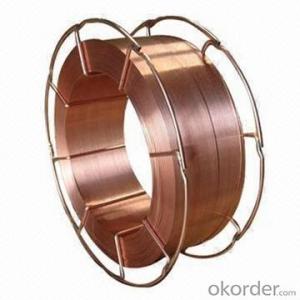
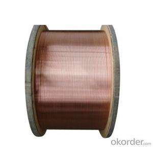
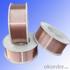
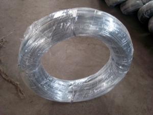
Competitive Price Hot Sale Best Price Solid welding wire ER70S-6
- Ref Price:
-

- Loading Port:
- Tianjin
- Payment Terms:
- TT OR LC
- Min Order Qty:
- 20 m.t.
- Supply Capability:
- 30000 m.t./month
Add to My Favorites
Follow us:
OKorder Service Pledge
Quality Product, Order Online Tracking, Timely Delivery
OKorder Financial Service
Credit Rating, Credit Services, Credit Purchasing
Quick Details
Place of Origin: Jiangsu, China (Mainland)
Model Number: AWS A5.18 ER70S-6
Approved by: CCS,ABS,LR,TUV,DB,FBTS,CWB
QMS: ISO9001 ISO14001
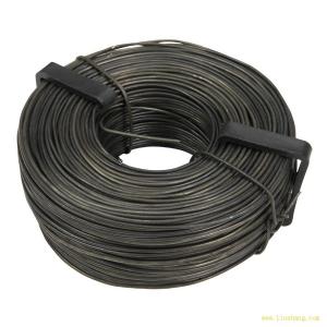
Packaging & Delivery
| Packaging Details: | Packing: net weight_1kg, 5kg, 15kg precision layer wound on plastic spool, each spool in a box, then boxes on wooden pallet. |
|---|
| Delivery Detail: | within 20 days after confirmed orders |
|---|
Specifications
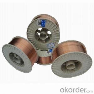
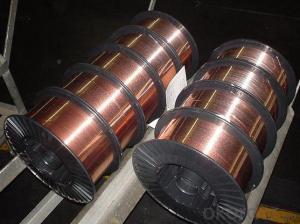
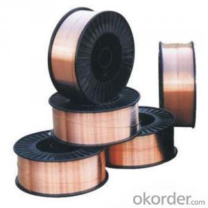
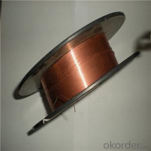
solid welding wire ER70S-6
1)Size:0.8-1.6mm
2)Suitable for vehicles,bridges,construction,machinery etc
3)spool pack
Report Suspicious Activity
Quick Details
Place of Origin: Jiangsu, China (Mainland)
Brand Name: DA Yunhe
Model Number: AWS A5.18 ER70S-6
Approved by: CCS,ABS,LR,TUV,DB,FBTS,CWB
QMS: ISO9001 ISO14001
Packaging & Delivery
| Packaging Details: | Packing: net weight_1kg, 5kg, 15kg precision layer wound on plastic spool, each spool in a box, then boxes on wooden pallet. |
|---|
| Delivery Detail: | within 20 days after confirmed orders |
|---|
Specifications
solid welding wire ER70S-6
1)Size:0.8-1.6mm
2)Suitable for vehicles,bridges,construction,machinery etc
3)spool pack
Product Description
| YH49-1 | YH50-6
| YH50-6 (YHG4Sil) | YH-60 | YH-70 |
| GB | ER49-1 | ER50-6 | ER50-6 | - | - |
| AWS | | ER70S-6 | ER70S-6 | - | - |
| DIN | | SG2 | SG3 | | |
| ISO EN14341 | | 3Si1 | 4Si1 | | |
GaugeΦ(mm) | 0.8-1.6 | 0.8-1.6 | 0.8-1.6 | 1.2-5.0 | 1.2-5.0 |
Welding wire chemical composition (%) | C | ≤0.11 | 0.06-0.14 | 0.06-0.14 | ≤0.12 | 0.07 |
Mn | 1.8-2.10 | 1.40-1.60 | 1.60-1.80 | 1.40-1.80 | 1.56 |
Si | 0.65-0.95 | 0.80-1.00 | 0.80-1.2 | 0.50-0.80 | 0.55 |
P | ≤0.030 | ≤0.025 | ≤0.025 | ≤0.025 | 0.012 |
S | ≤0.030 | ≤0.025 | ≤0.025 | ≤0.020 | 0.003 |
Cr | ≤0.20 | ≤0.15 | ≤0.15 | ≤0.45 | 0.07 |
Ni | ≤0.30 | ≤0.15 | ≤0.15 | - | 0.94 |
Mo | - | ≤0.15 | ≤0.15 | ≤0.30 | - |
Ti | | ≤0.15 | ≤0.15 | ≤0.15 | 0.012 |
Cu | ≤0.50 | ≤0.50 | ≤0.50 | ≤0.20 | 0.15 |
Mechanical properties of deposited metal | Yield Strengthσs(Mpa) | ≥372 | ≥420 | ≥420 | ≥450 | ≥530 |
Tensile Strengthσb(Mpa) | ≥490 | ≥500 | ≥500 | ≥570 | ≥650 |
Elongationδ5(%) | ≥20 | ≥22 | ≥20 | ≥19 | ≥20 |
Akv impact J(℃) | ≥47 (room temperature) | ≥27(-30) | ≥47(-20) | ≥27(-20) | ≥40(-30) |
Shielded gas | C02 | Ar+C02 | Ar+C02 | C02 | CO2 |
Application | YH49-1 | Used to welding steel for ship building)A32,E32,D32,A36,E36,D36) and mild steel products with strength at 490N/mm2 degree, such as mild alloy steel 16Mn,15Mn etc. to produce turn ace, rubes for vessel, contained building etc. |
YH50-6
(3Sil) | Apply to ships of steel (A, B, D, E, A36, D36, E36) and at the same level of intensity of low-alloy steel welding important structures. Such as containers, vehicles, construction machinery, semi-automatic and automatic gas shielded welding. |
YH50-6 (YHG4Sil) |
YH-60 | Used to coal machinery and heavy machinery for welding, oil pipe lines etc. |
YH-70 | Used to coal machinery and heavy machinery for welding, oil pipe lines etc. |
- Q: I am doing wiring in my shed on preexisting light fixtures and outlets. the wiring that was disconnect from that carried the electricity to it. What I am trying to do is have all the light fixtures work of an extension cord. I have another extension wire connected to that with the +, - and 0 showing. The fixtures have 3 wires coming out of them what I think to be the power in, power out, and switch. On the fixture on the end I connected my extension cord thing and it work, BUT only that one. The rest of the fixtures did not work, I do see anything wrong. What I thought was that I was connecting to the switch wire so I changed it and it just buzzed with blue light. What is going on?
- Oh Abdullah, instead read Alexander Pope's An Essay on Criticism, and read slowly the lines a little learning is a dangerous thing and fools rush in where angels fear to tread, then go find someone a little less hyper and a little less dangerous to help, or else somebody's going to get hurt!
- Q: I bought a single pole dimmer switch to install in my dining room and when I took the old switch out nothing looked right. There are two wires which were joined together by another single wire which was attached to the top screw. There was another single wire (I believe the ground wire) attached to the bottom screw. I disconnected the first two wires and attached them separately to the black wires on the dimmer and attached the ground wires together. It didn't work. I've tired several different times with no luck. I put the wires back the way they were and attached them to the old switch and they no longer work ether. Help! How can I fix this problem? The old wires appear to be a very thick copper covered in black plastic and cloth.....
- The 'answerer' Justin K thinks you have knob and tube wiring. A lot of early electrical installations were done in the old days with out a ground, many types of early 'romex' did not include a ground. You may or may not have 'knob and tube' wiring - but it really dose not matter. The two wires which were joined together and had a third wire attached are the hot wires. The other wire (lower screw terminal) is the 'load' wire - it goes out to your light fixture. The reason the those 2 wires were attached together is that one of them is hot, and the other wire is a 'feed' to supply power to your next switch or receptacle. I am an electrical contractor, this is how I would fix the problem - I'm not suggesting that you do it though. #1 turn the breaker/fuse back on. #2 use a voltage tester to determine which wire is now hot. #3 touch the hot wire to the other wires 1 at a time. The hot wire when it is touching the 'load' wire will turn on the lighting fixture. Mark the 'load' wire with some black electrical tape. #4 turn the power back off #5 attach the marked 'load' wire to one of the switch terminals. #6 take the other 2 wires (incoming power, and the out going power) and join them together with a third wire ---LIKE IT WAS ORIGINALLY. Place that third onto the other terminal of the switch. it dose not mater which terminals you use - it will work just fine.
- Q: my light stopped working ( a chandalier ). It has brown wires, blue wires, red wires, beige wires, and white wires.
- If you have an Ohmmeter you can trace the chandelier wiring out. Each socket in the chandelier has two connections, the threaded part of the base and the very bottom of the base. The safest way to wire it is to run the hot to the bottom of the base and the neutral to the threaded part of the socket. Anyway you should be able to ohm each wire out to see where they go, then hook all the wires going to the bottom together and to the black wire in the junction box, then all the wired going to the threaded connection together and to the white wire in the junction box.
- Q: How do current carrying wires produce magnetism... Explain, give sites and clarify.
- i'm uncertain we've a sparkling theoretical answer to this in spite of the incontrovertible fact that it relatively is a demonstrable actuality that shifting expenses have an result on different shifting or movable expenses.even while there is not any internet fee glaring it relatively is summarized as magnetism
- Q: Hello, I have a 4 year old Trane XR12 unit. Recently the compressor fan is noisy, and now stops when when under power after 5-10 min. The main fuses and breakers are fine, the fan spins freely when turned, the contactor pulls in fine, the dual capacitor checks out. But, the wiring of the capacitor does not match wire diagrams. Could this have caused the fan motor to prematurely fail?..............................Terminal: C red wire, FAN brown wire, HERM has both orange and purple. Schematic shows the purple wire should be with red wire on common C. The purple also leads to fan.
- Hi, I looked at the schematic on-line. If you still have the original fan motor in the unit then you are correct. The center terminal on the capacitor should have the red wire from the T1 terminal of the contactor, the red wire from the compressor, and the purple wire from the fan. The FAN terminal should have the brown wire from the fan. The HERM terminal should have the orange wire from the compressor. The black wire from the fan and the black/blue wire from the compressor should lead back to the T2 terminal of the contactor. Again, that is if the motor is the original motor. If it was replaced at some point in time, the wiring colors can change from manufacturer to manufacturer, in which case it's possible that the new motor is wired correctly. There should be a diagram on the motor to show you the correct wiring configuration.
- Q: I am getting these 2 CVR 12's 4 ohm dvc and i am wiring them for a 2 ohm load (parallel). When you run a wire from voice coil 1 positive to voice coil 2 positive, then to amp. and the same for negative, what is the wire that is connecting the voice coils? is it a power wire, ground wire, speaker wire? please help!
- This one is the terrific capacitor. Pyramid CAP300DBL 3-Farad extreme-overall performance digital skill Capacitor Technical info - 3 Farad Surge - Polished metallic end - Platinum-Plated sturdy Brass Hardware - computing gadget controlled On/Off - digital Voltage exhibit
- Q: I need to get some wire to hook my capacitor to my amp and every wire I see says that it's power/ground cable wire. Does this mean it's power wire? Or ground wire? Or does it mean you can use it for both?
- you can use it for both same stuff
- Q: I am wiring a GFCI receptacle with two regular receptacles after it.So before the GFCI I have my 12/2 wire from where it will hook into the box (the line side), after it I have my wire going to the two other receptacles (the load side).Well the GFCI receptacle has screw terminals for the line HOT and WHITE wires as well as a GROUND. On the bottom it has screw terminals for the load side but ONLY the HOT and WHITE, no ground screw.Does this mean that I don't hook up the ground for the load wire or does it mean I have to pigtail the ground to the same screw the line ground is using?I didn't want to assume that I connect the line and load grounds out of fear I was circumventing the GFCI.
- Maybe you got a bad GFI Recepticle!!! all the ones I ever worked with have a place for the ground wire!!! Take another look at it!!! maybe someone didnt put the green screw in?? Bring it back to the store and get another one!!!
- Q: i have a 300x1 @ 4ohm and 600x1 @ 2ohms, i wanna hook it up at 2 ohms what gauge wiring kit should i get?
- well,i didnt know what kind of amp that you have,so probably its true 300w or not. but my suggestion is for your own equipment safety you should use min. 4 ga with 50a, coz i see here you try to bridge it. try tsunami they good and real 4ga if they said 4ga.
- Q: can someone tell me what wire arcing is?
- A very complex subject! Generally, the arc itself is a small area of plasma between to conductors at different potentials.. If the wires never touch, a high potential/voltage is required to get it started. Once initiated, the voltage across the arc becomes quite low (around 20V) even at high currents. There are many other interesting features like the arc impedance has an area of negative differential resistance. Arcs in house wiring are categorized into to camps. These are series arcs and paralell arcs. Series arcs are those that are in series with the load. They happen when a wire breaks and starts to separate. As the wire pulls apart the arc strikes and a plasma is initiated. These arcs are low in current (below the breaker's rating) and will not be detected by the circuit breaker. They can persist for a long time just sizzling away and can start fires. Parallel arcs are when the line and return wires have insulation failure and short together. They tend to have very high currents and quickly either blow themselves open or go to a 'bolted' fault (hard short circuit) and trip the breaker. They too can start fires in spectacular fashion. As I said, its very complex and I could go on for pages ... I worked on arc research for a number of years trying to devise ways of detecting arcs back at the circuit breaker box using current and voltage signatures. It should also be mentioned that arcs act very differently with AC voltage verses DC voltage. AC arcs tend to extinguish at the 60Hz crossovers (when the current is zero) and must be restruck each cycle. Because of arcs, and recent research, you will now find special circuit breakers on the shelf at your local hardware store that have extra capabilities related to detecting arcs. If there is a specific question that you have regarding arcs, post more details or send me an email.