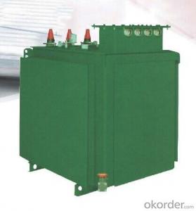
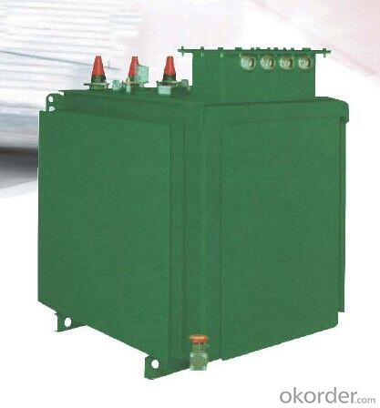
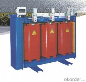
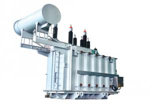
SBH16-M-D Type Amporphous Metal Underground Distribution Transformer
- Ref Price:
-

- Loading Port:
- Shanghai
- Payment Terms:
- TT OR LC
- Min Order Qty:
- 1 unit
- Supply Capability:
- 1000 unit/month
OKorder Service Pledge
Quality Product, Order Online Tracking, Timely Delivery
OKorder Financial Service
Credit Rating, Credit Services, Credit Purchasing
You Might Also Like


- Q: High power transformers are very common, for obvious reasons. Much unlike homemade transformers that I've ever built, only out of tiny enameled #26 wire, that wouldn't power anything practical.I've tried using wire as large as #6 wire to wrap a homemade transformer, as what would be needed to connect externally to 10 kVA transformers, but that simply isn't practical. The wire is simply too stiff to wrap it in tight windings.Consider the example of a 225 kVA three phase transformer, that carries about 300 Amps of current on each of its secondaries that are 277 Volts. Externally, I'd need to connect with 400 kcmil wire, that is almost an inch in total diameter. What exactly do they do in order to build transformers at this high power?Do they parallel a whole bunch of tiny windings?Do they use a cooling fluid, so that tiny wire can have a much greater ampacity?Or do they also use big wire, but the way it is constructed somehow relieves the strain resulting from wrapping it? Heat treating the metal, perhaps.
- Wire must be chosen to that the current density does not cause them to overheat.
- Q: What is the meaning of the Y D11 on the transformer?
- Yn d11 said: high side is a star-shaped wiring with a neutral point of the lead-out, low-side side of the triangle wiring. Using 11-point connection, that is, high-voltage side of the line voltage ahead of the low voltage side line voltage of 30 degrees.
- Q: Why is the transformer ah?
- Transformer principle is based on the principle of electromagnetic induction made, the transformer has two separate coil sharing a core. Respectively, called the primary coil and secondary coil. When the direction and size of the alternating current change with time, when the transformer is connected to the alternating current, the alternating magnetic field is generated in the core of the transformer, and the AC voltage of the same frequency is induced in the secondary. The turns ratio of the primary winding of the transformer Equal to the voltage ratio. Transformer can only change the AC voltage, can not change the DC voltage, because the DC direction and size is constant, through the transformer will not produce alternating magnetic field.
- Q: I know that both at some point were comics made by Marvel and that Thundercats was animated by a japanese studio and Transformers had an original series in japan but was here in america first. That's the info I have but what is what? And please no guessing if you don't know please don't play favorites between american and japanese cartoons, ok?
- Transformers okorder
- Q: The book said the main transformer power failure operation should first stop the load side after the power side, is to prevent the transformer in the case of multi-power reverse charging. What is the transformer anti-charging here? What's wrong?
- You can explain the specific situation, your multi-power situation is what kind of situation, because we have not seen you refer to the "book"
- Q: I have 14 gauge wire and some 28 gauge wire. Do both lengths of wire have to be insulated? Is it as easy as winding the 14gauge wire top to bottom and then do the 28 gauge wire top to bottom also? I'm guessing this is a step up transformer because the battery is going through the 14 gauge wire and then the lightbulb is hooked to the 28 gauge wire?Does the direction on winding matter at all? Say, CW for the 14g and then CW with the 28 gauge?
- ferrite rods are not customarily used for transformers. at RF they are sometimes used as a core for a loop antenna. your application sounds like an ignition coil as you need an interrupter on the DC input (like points on a car ignition). the primary wire (14 gauge) would just be a few turns and not likely to run the full length top to bottom, the secondary (28 gauge) would be a lot of turns like 10 or 20 times as many. direction of winding would not matter in this application as capacitive coupling between the windings should be insignificant. all wire has to be insulated as a shorted turn spoils the transformer effect. wire used for transformers is customarily insulated with lacquer as plastic adds too much bulk to make tight windings. if you already have bare wire, then you made have some success by dipping the wire in lacquer paint first. it sounds like you are duplicating a project you have seen elsewhere. without knowing the source, it is hard for us to guess what the circuit parameters need to be for the transformer. but as i pointed out initially, i am skeptical that you will get this to function in the manner you are expecting. AC power transformers of the kind that use these wire gauges always use a torroidal core ferrite, never a rod. static DC cannot be transformed at all.
- Q: 50kva transformer price
- You have a problem is the voltage level and model do not know, can not set the price. The capacity is 50 kVA. If it is 10000 volts change 400 volts S11 50 kVA is about 9,000 yuan, S9 7500-8000, S7 is about 7000.
- Q: Altium designer DXP transformer in the same name how to change?
- The same name is a painting of about 2-3mil radius of the solid circle, can not directly change, must be copied from the source file to the schematic library file can be changed, that is, to re-create schematic symbols.
- Q: I would like to get my grandchild all the transformer movie dvds but don't know the names of all of them. please help and thanks
- Transformers, Transformers: Revenge of The Fallen, and Transformers: Dark of the Moon(comes out September 30). Hope I helped.
- Q: !!! I took a cardboard cylinder from a used firework, dug out all the crap, wrapped 160 turns of tinned copper wire on the outside tight and evenly so it is a beautiful solenoid, held it in place with 2 rubber bands. That was the secondary. Then I wrapped an insulated steel wire around a screwdriver shaft 10 times, stretched it out a little inserted a chopstick into this primary and inserted the chopstick into the firework. I then held it all in place with tissue paper and tape and wired the primary up to a pulsed DC circuit which was made of 3.0 volts wired to a steel file which I rubbed the electrode across. The secondary was wired to a current detector but I got no signal! Why is there zero inductance in my transformer and why is there no current at all? It can't even light up a small lightbulb!!
- I think your current detector was not good enough. Was it a bulb? It wouldn't supply enough current for one. I'd suggest you need a more sensitive indicator. What you should see is about 48V. AC on the secondary, plus some more due to the inductance of the primary. Your electrode you rub on the file must be very small, such as the end of a wire, to give an interruption. You could probably get an indication on a digital multimeter on an AC range. Just don't expect it to be an accurate reading. If you're game, you could hold one end of your secondary in your fingers, and touch the other end to your tongue, then do the file thing. But you might only want to try once! I often use my tongue for low voltage indications. But 48V. would be a bit much for me. Ouch!
Send your message to us
SBH16-M-D Type Amporphous Metal Underground Distribution Transformer
- Ref Price:
-
- Loading Port:
- Shanghai
- Payment Terms:
- TT OR LC
- Min Order Qty:
- 1 unit
- Supply Capability:
- 1000 unit/month
OKorder Service Pledge
Quality Product, Order Online Tracking, Timely Delivery
OKorder Financial Service
Credit Rating, Credit Services, Credit Purchasing
Similar products
Hot products


Hot Searches
Related keywords

