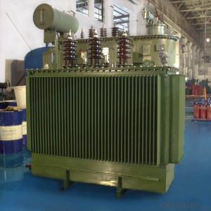


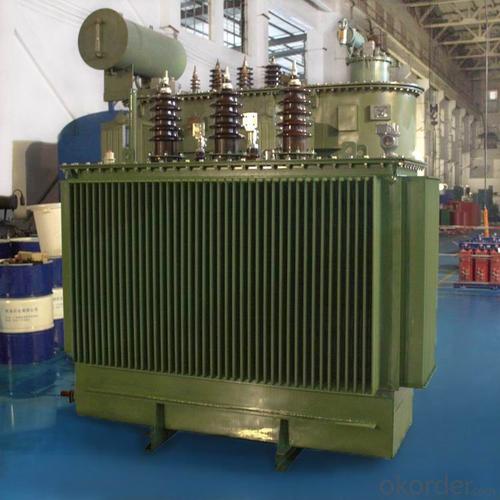


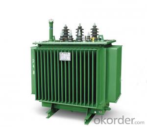
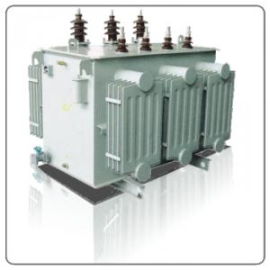
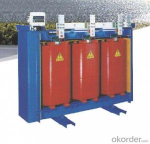
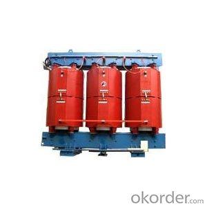
SBH15-M amorphous alloy oil immersed transformer
- Ref Price:
-

- Loading Port:
- Guangzhou
- Payment Terms:
- TT OR LC
- Min Order Qty:
- 1 pc
- Supply Capability:
- 1000 pc/month
OKorder Service Pledge
OKorder Financial Service
You Might Also Like


Specification
Product Introduction
With stable & reliable quality for strong low current supply; Have strong short-circuit resistant and good thermal stability.. Can drop the no-load losses substantially Save energy Low cost & High return investment
Voltage Available: 10kV, 11kV, 20kV,22kV,33kV,35kV..
In order to better meet people's high demand for saving energy and resources, our company develops a new product Amorphous Alloy Omniseal Distribution Transformer, which is an advanced transformer made with amorphous alloy magnetic iron core and will get lower consumption.
Amorphous Alloy is a new type energy saving material, which is not exist crystal structure, with small magnetizing power and low impedance can reduce eddy current losses. Uses this kind of material as core, can drop the no load losses substantially.
Product Parameter
| Item NO. | Group Voltage & Tap Range | Connection Symbol | No-load power(W) | Load Loss(W) | No-load Current(%) | Short Circuit Impedance(%) | Dimension | Gauge(mm) | Weight(kg) | ||
| L*W*H | |||||||||||
| High Voltage(KV) | Tapping Variation | Low Voltage(V) | (mm) | ||||||||
| S(B)H15-M-30/10 | 6 | ±5% | 0.4 | Dyn11 | 33 | 600 | 1.5 | 4 | 400 | 345 | |
| S(B)H15-M-50/10 | 6.3 | ±2*2.5% | 43 | 870 | 1.2 | 480 | |||||
| S(B)H15-M-63/10 | 10 | 50 | 1040 | 1.1 | 545 | ||||||
| S(B)H15-M-80/10 | 10.5 | 60 | 1250 | 1 | 625 | ||||||
| S(B)H15-M-100/10 | 11 | 75 | 1500 | 0.9 | 710 | ||||||
| S(B)H15-M-125/10 | 85 | 1800 | 0.8 | 550 | 850 | ||||||
| S(B)H15-M-160/10 | 100 | 2200 | 0.6 | 940 | |||||||
| S(B)H15-M-200/10 | 120 | 2600 | 0.6 | 1085 | |||||||
| S(B)H15-M-250/10 | 140 | 3050 | 0.6 | 1265 | |||||||
| S(B)H15-M-315/10 | 170 | 3650 | 0.5 | 1485 | |||||||
| S(B)H15-M-400/10 | 200 | 4300 | 0.5 | 660 | 1860 | ||||||
| S(B)H15-M-500/10 | 240 | 5150 | 0.5 | 2180 | |||||||
| S(B)H15-M-630/10 | 320 | 6200 | 0.3 | 4.5 | 2480 | ||||||
| S(B)H15-M-800/10 | 380 | 7500 | 0.3 | 820 | 3048 | ||||||
| S(B)H15-M-1000/10 | 450 | 10300 | 0.3 | 3420 | |||||||
| S(B)H15-M-1250/10 | 530 | 12000 | 0.2 | 4218 | |||||||
| S(B)H15-M-1600/10 | 630 | 14500 | 0.2 | 4922 | |||||||
| S(B)H15-M-2000/10 | 750 | 18300 | 0.2 | 5 | 6150 | ||||||
| S(B)H15-M-2500/10 | 900 | 21200 | 0.2 | ||||||||
Product Features
1. SH15 oil immersed transformer
2. Adopts Amorphous core
3. Only 1/3 losses of normal transformers
4. With good heat dispassion
Rating Capacity: From 100kVA ~2500kVA Available!
Voltage: 10kV~35kV Available!
Product Installation
1. Installation: outdoor
2. Altitude: <1000m< span="">
3. Highest air temperature: +45 °C
4. Lowest air temperature: -25°C
5. Sunshine intensity: 0.1w/cm2(wind 0.5m/s)
6. Rain proof level: Level 3
7. Earthquake resistance ability: The ground level acceleration of 0.2g
8.The inclination of the installation site: <3°< span="">


- Q: If a transformer rating 240vac 50hz being supplied by a source 240vac 60hz,will it get hotter than by 240vac 50hz source?
- Inductive Reactance increases proportionally with frequency. Therefore, if the supply voltage remains the same but the frequency increases, the impedance increases. This will lead to an increase in heat. If the supply voltage remains the same but the frequency decreases, the impedance decreases, which means that less heat is produced. The answer to your question is NO.
- Q: I know that before the 2007 release of transformers and this years sequel there were various animated tv series and comics. I just want to know what the live action movies are actually based on. Like are the movies just real life portrayls of the the animated story line? Or are they original plots just based on the ideas of autobots, decpticons and there home cybertron?If the plots for the movies are based off the comics of series (like the x men movies) what could be the possible plot for the 3rd installment of the film franchise?
- Micheal Bay just blowing stuff up with Robots. Would be a miracle if they used some cartoon or comic book story.
- Q: Rules for the operation of cooling devices for oil - cooled transformers
- E, strong oil cycle air-cooled and strong oil circulating water-cooled transformers, when the cooling system failure to remove all the cooler, allowing the rated load to run for 20 minutes, such as 20 minutes after the top of the oil temperature has not reached 75 ℃, then allowed to rise to 75 ℃ , But in this state the maximum time to run no more than 1 hour. ?F, under normal circumstances, the transformer no-load operation, the cooling device two groups of work, a group of auxiliary, a group of spare, the remaining disabled; transformer low temperature, light load, the four groups of work: a group of auxiliary, a group of spare, the rest Deactivated; transformer high temperature, full load, a group of auxiliary, a group of spare, the rest all into work.
- Q: 100kVA transformer can withstand much of the current? What is its formula?
- For safety insurance, the current density is about 3.0, S = 144.34 / 3 = 50 (about) So take the 50 square cable can be.
- Q: dear sircan you please tell me the different Between the indoorr and outdoor distributionn transformer 11kv in applications and designwith our best regards
- To be honest, I don't believe that's correct
- Q: I have a standard transformer with 7 wires:2 black2 red2 yellow1 red/yellow stripedWhat connections do these wires correspond to?That is, which should connect internally to the primary coil, the secondary coil, and coil-taps (based on the number of wires, I assume that the secondary coil is tapped).I must determine this in order to connect the wires (externally) appropriately.Any help is greatly appreciated!
- Raptor gave good info. I would add just a few points: 1. The high voltage winding usually has the smaller gauge wire. 2. The high voltage (primary) winding also usually has a higher DC resistance and fundamental frequency impedance than the secondary. 3. Be sure to scrape the insulation off the wires before checking the resistance. Many years ago, an idiot I was working with didn't recognize that the wires had enamel insulation on them, and connected the transformer backwards. It was a 480 V / 1 V (or so) instrument transformer. We lost a lot of good equipment and nearly lost people because of that screwup. The recorder saw 2 kV before it died.
- Q: I have a 25 volt 2 amp transformer from radioshack and a non push dimmer from walmart. The dimmer has two black wires and one green. The transformer has on one side two yellows and a black and on the other side two blacks. I need to know how to hook the dimmer up to an outlet then how to wire it to the transformer.
- The number of wires on the transformer don't match with the stated voltages. The two blacks are probably the 120 volts input (assuming this is the US) but the 3 wires on the secondary imply you have a center-tap secondary, possibly 25 volts center tapped at 2 amps. I'm also assuming that the hot wire is sized to operate on 25 volts. The transformer should come with some sort of labels for the wires, if not take it back and get one that does. Once you get the transformer straightened out, here is a wiring list. AC hot from line cord black wire to one side of a 1 amp fuse holder AC neutral from line cord white wire to one of the line connections of the transformer AC ground from line cord green wire to transformer case and to case of dimmer (green) and to metal case this is all mounted in. Other side of fuse holder to one of black wires of dimmer Other black wire from dimmer to the second of the line connections of the transformer One of secondary wires on transformer to one side of the hot wire Other secondary wire on transformer to other side of the hot wire Tie the center tap of the secondary, if there is one, to ground. If not, tie one of the secondary wires to ground. You will note that I included a small 1 amp fuse. You can get a small metal box to mount this stuff in, or a electrical junction box. The latter is better as it has punchouts for cable in and out. Be sure to clamp the wires where they enter and leave the box.
- Q: I bought a Neon Sign Transformer over OKorder and for a while it worked great. I used it to power a Jacobs Ladder (I wired the transformer straight to the Jacobs ladder). However, now the transformer will turn on the jacobs ladder but after a couple of seconds it will shut off and sometimes make a buzzing noise. What is wrong with it and how can I fix it?
- You have 2 problems there. 1. Voltage; 2. Frequency. In this case, both are against you. NZ has 50Hz mains frequency at 240V. If you are really lucky, the transformer will have dual windings on the primary, or a 220/240V. tap. If you don't know what you are doing, consult an electrician or electronics tech. to have them check whether it is dual voltage, and change it. The frequency difference can mean a little less efficiency, the transformer may get a little warmer in operation. But it should be fine. You only other options are to replace the transformer (get one for dual voltages?), or use a 240/110V stepdown transformer ahead of it. The stepdown transformer must have a sufficient power rating for the job.
- Q: What is the meaning of the transformer 'turns ratio'? what's the effect?
- The number of turns of the primary coil (that is, the number of turns around the coil) and the number of secondary turns. Turns ratio and voltage ratio is proportional. For example, 220 volts to 10 volts voltage ratio is 220: 10, turns ratio should also be 220: 10, such as the primary is 2200 laps, the secondary should be 100 laps. Multi-turn ratio is the number of turns of the secondary output and the primary correspondence. A variety of turns ratio is to allow a sensor device is used for a variety of heat treatment process. I remember answering your question? how? Do not believe? 'U1 / U2 = n1 / n2' "/" Or ":" read here as "than", the size of the ratio is that you say the size of the divisor, you put it when the division can also be seen. U1 / U2 = n1 / n2 'U1 denotes the primary voltage of the transformer, U2 denotes the secondary voltage of the transformer, n1 denotes the number of primary turns of the transformer, that is, the number of turns, n2 denotes the secondary turns of the transformer, The number of turns, n1 / n2 is the turns ratio. The meaning of this formula is: transformer primary and secondary voltage ratio = its primary and secondary turns ratio (turns ratio) I do not know you can not understand, do not understand I can do nothing
- Q: If it is powered by a DC source, will there be a Back EMF generated? Why/Why Not?Obviously, there will be a higher current flowing than that of a AC supplied transformer, but I don't know why.Thanks.
- I once powered my transformer from DC with LED on other end. the LED glowed for a fraction of second and then went off
Send your message to us
SBH15-M amorphous alloy oil immersed transformer
- Ref Price:
-
- Loading Port:
- Guangzhou
- Payment Terms:
- TT OR LC
- Min Order Qty:
- 1 pc
- Supply Capability:
- 1000 pc/month
OKorder Service Pledge
OKorder Financial Service
Similar products

Hot products


Hot Searches

