
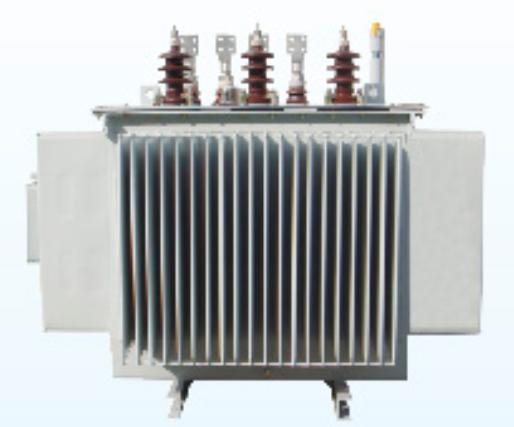
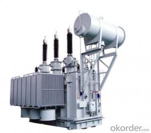
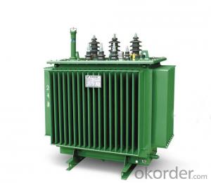
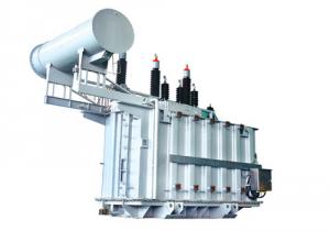
Oil immersed Distribution Transformers 6-10kV
- Ref Price:
-

- Loading Port:
- China Main Port
- Payment Terms:
- TT OR LC
- Min Order Qty:
- -
- Supply Capability:
- -
OKorder Service Pledge
OKorder Financial Service
You Might Also Like


6-10kV Oil-immersed DistributionTransformers

1. Introduction
6-10kV oil-immersed distributiontransformers with capacity 30-3150kVA are suitable for 6-10kV distributionnetwork system. Product complies with GB/T6451-2008 standards.
Type 9, 11 and 13 are classified byloss standard. Two types of oil tank are provided, they are sealed corrugatedradiating and sheet radiator. Voltage can be adjusted with load through switchinstalled.
2. Characteristics
Fully sealed corrugated tank has corrugatedsheet for transformer oil natural cooling. There is no oil storage cabinetneeded, so the oil is completely isolated from air. This design slows down theaging of oil, eliminates maintenance and extends the transformer life.
3. Technical parameters
Technical parameters of S9-Mcorrugated tank transformers
Code | Rated capacity (kVA) | rated voltage(kV) | Loss (xW) | Short Circuit impedance (%) | No Load Current (%) | Connection Symbol | Weight (kg) |
Dimension L*W*H (mm) | mm | |||||
HV | LV | No Load | Load | |||||||||||
Body | Oil | Total | ||||||||||||
S9-M-100 | 100 |
10 6.3 6 | 6.3 6 | 290 | 1500/1580 |
4.0 | 1.8 |
Yyn0 Dyn11 | 285 | 105 | 515 | 800x680x1030 | 550/550 | |
S9-M-125 | 125 | 340 | 1800/1890 | 1.7 | 355 | 110 | 625 | 920x700x1060 | 550/550 | |||||
S9-M-160 | 160 | 400 | 2200/2310 | 1.6 | 420 | 130 | 740 | 970x730x1070 | 550/550 | |||||
S9-M-200 | 200 | 480 | 2600/2730 | 1.5 | 475 | 160 | 825 | 1020x740x1085 | 550/550 | |||||
S9-M-315 | 315 | 670 | 3650/3830 | 1.4 | 710 | 205 | 1200 | 1350x740x1115 | 550/550 | |||||
S9-M-500 | 500 | 960 | 5150/5410 | 1.2 | 925 | 285 | 1575 | 1470x795x1310 | 660/660 | |||||
S9-M-630 | 630 | 1200 | 6200 |
4.5 | 1.1 | 1085 | 320 | 1835 | 1540x830x1360 | 660/660 | ||||
S9-M-800 | 800 | 1400 | 7500 | 1.0 | 1375 | 435 | 2340 | 1630x920x1430 | 820/820 | |||||
S9-M-1000 | 1000 | 1700 | 10300 | 1.0 | 1480 | 485 | 2600 | 1755x1035x1450 | 820/820 | |||||
S9-M-1250 | 1250 | 1950 | 12000 | 0.9 | 1760 | 575 | 3135 | 1870x1120x1540 | 820/820 | |||||
S9-M-1600 | 1600 | 2400 | 14500 | 0.8 | 2125 | 700 | 3795 | 1970x1170x1645 | 820/820 | |||||
Technicalparameters for S11-M corrugated tank transformers
Code | Rated capacity (kVA) | rated voltage(kV) | Loss (xW) | Short Circuit impedance (%) | No Load Current (%) | Connection Symbol | Weight (kg) | Dimension L*W*H (mm) | mm | ||||
HV | LV | No Load | Load |
|
|
| Body | Oil | Total |
|
| ||
S11-M-160/10 | 160 |
10 6.3 6 |
0.4 6.3 6 | 280 | 2200/2310 |
4.0 | 1.6 |
Yyn0 Dyn11 | 490 | 100 | 795 | 1135x713x180 | 550/550 |
S11-M-200/10 | 200 | 340 | 2600/2730 | 1.5 | 540 | 175 | 880 | 1168x738x1200 | 550/550 | ||||
S11-M-250/10 | 250 | 400 | 3050/3200 | 1.4 | 665 | 200 | 1025 | 1240x780x1240 | 550/550 | ||||
S11-M-315/10 | 315 | 480 | 3650/3830 | 1.3 | 730 | 220 | 1155 | 1300x835x1265 | 550/550 | ||||
S11-M-400/10 | 400 | 570 | 4300/4520 | 1.2 | 895 | 300 | 1390 | 1390x905x1310 | 550/550 | ||||
S11-M-500/10 | 500 | 680 | 5150/5410 | 1.1 | 1025 | 360 | 1650 | 1470x965x1365 | 550/550 | ||||
S11-M-630/10 | 630 |
0.4 | 810 | 6200 |
4.5
5.5 | 1.0 | 1650 | 415 | 2260 | 1575x1010x1430 | 660/660 | ||
S11-M-800/10 | 800 | 980 | 7500 | 1.0 | 1510 | 470 | 2550 | 1685x940x1545 | 820/820 | ||||
S11-M-1000/10 | 1000 | 1150 | 10300 | 0.9 |
Dyn11 | 1640 | 650 | 3070 | 2180x1075x1655 | 820/820 | |||
S11-M-1250/10 | 1250 | 1360 | 12800 | 0.8 | 2010 | 820 | 3700 | 2310x1310x1715 | 820/820 | ||||
S11-M-1600/10 | 1600 | 1640 | 14500 | 0.8 | 2420 | 990 | 4470 | 2460x1514x1920 | 820/820 | ||||
S11-M-2000/10 | 2000 | 2240 | 16830 | 0.8 | 2860 | 1120 | 5050 | 2782x1600x2040 | 820/820 | ||||
S11-M-2500/10 | 2500 | 2640 | 19550 | 0.8 | 3195 | 1155 | 5912 | 2500x2060x2010 | 820/820 | ||||
Parameters for 6-10kV SZ11 OLTC Transformers
Code | Rated capacity (kVA) | Rated voltage (kV) |
| Loss(xW) | Short Circuit impedance (%) | No Load Current (%) | Connection Type Symbol | Weight (kg) | Dimension L*W*H(mm) | mm) | ||||
HV | LV | No Load | Load | Body | Oil | Total | ||||||||
S11-M-200/10 | 200 |
10 6.3 6 |
0.4 |
±4x2.5%
| 0.48 | 3.06 |
4.0 | 1.5 |
Yyn0 Dyn11 | 531 | 241 | 1058 | 1510x820x1460 | 550/550 |
S11-M-250/10 | 250 | 0.56 | 3.60 | 1.4 | 630 | 350 | 1400 | 1740x1020x1440 | 550/550 | |||||
S11-M-315/10 | 315 | 0.67 | 4.32 | 1.4 | 860 | 280 | 1630 | 1790x1050x1570 | 550/550 | |||||
S11-M-400/10 | 400 | 0.80 | 5.22 | 1.3 | 910 | 400 | 1740 | 1830x1120x1630 | 660/660 | |||||
S11-M-500/10 | 500 | 0.96 | 5.21 | 1.2 | 1080 | 460 | 2068 | 1900x1230x1780 | 660/660 | |||||
S11-M-630/10 | 630 | 1.20 | 7.65 | 1.1 | 1396 | 611 | 2661 | 2010x1320x1930 | 660/660 | |||||
S11-M-800/10 | 800 | 1.40 | 9.36 | 1.0 | 1650 | 780 | 3220 | 2280x1370x2220 | 820/820 | |||||
S11-M-1000/10 | 1000 | 1.70 | 10.98 | 1.0 | 2083 | 843 | 4240 | 2170x1160x2320 | 820/820 | |||||
S11-M-1250/10 | 1250 | 1.95 | 13.05 | 0.9 | 2390 | 1100 | 4950 | 2510x1310x2630 | 820/820 | |||||
S11-M-1600/10 | 1600 | 2.40 | 15.00 | 0.8 | 2900 | 1065 | 5235 | 2570x1382x2650 | 820/820 | |||||
Note: The above parameter before slash is forYyn0 connection type and after slash is for Dyn11 connection type.
- Q: 50KVA transformer maximum load is how much?
- 50KVA transformer can bring the maximum load is, 1.45 * 50 = 72.5A or so
- Q: How to understand the secondary side of the transformer
- The transformer consists of iron core (or core) and coil, the coil has two or more than the winding, which connected to the power supply winding called the primary coil (a test), the rest of the winding called secondary (secondary side). The basic principle of the transformer is the principle of electromagnetic induction, now single-phase double-winding transformer as an example to illustrate its basic working principle: When the primary winding with voltage U1, the current I1 flow, in the core to produce alternating magnetic flux , These magnetic flux known as the main flux, in its role, both sides of the winding were induced potential E1, E2. Transformer two sets of coil turns are N1 and N2, N1 for the primary, N2 for the secondary. In the primary coil plus an AC voltage, the secondary coil will produce both ends of the induced electromotive force. When N2> N1, its induction The electromotive force is higher than the primary voltage. This transformer is called a step-up transformer: when N2 <N1, its induced electromotive force is lower than the primary voltage, which is called a descending transformer. Primary secondary voltage and coil The number has the following relationship: U1 / U2 = N1 / N2 Suppose that n is the voltage ratio (turns ratio). When n <1, then N1> N2, U1> U2, the transformer is a step-down transformer, otherwise it is a step-up transformer.
- Q: Is the LTC transformer a regulated voltage transformer?
- OLTC (on load tap changer) On-load tap-changer NLTC (no Load tap changer) No load regulator The above two switch switches are used for transformer voltage regulation.
- Q: For a project, I need a sine wave with an RMS amplitude of 1000 V at least.I have a function generator that only makes sine waves at most of 7 V RMS.I have a neon transformer w/ a 120 V primary and a 3,300 V secondary and a step down transformer w/ a 120 V primary and 16 V secondary, which is used backwards.Well, I can only get 585 V max. I decided to get some low power step down transformers (Hammond Mfg. 162 series) w/ dual primary and secondary windings. so I can try different combination of step up.I thought the smaller the core would be less of a load for the generator. I get 30 V out of the HVAC tran. (10 VA rating) when the big transformer is hooked up, but for a Hammond w/ a similar winding ratio and (1.1 VA) w/ a similar winding ratio, but I can only get like very little out of the big transformer when hooked up.Is there another factor. I read something about transformer impedance, I was thinking of doing a quick measurement of that on them.
- You are confusing VA (power ratings) with transformer ratios 120/16 7.5 :1 3300/120 27.5 : 1 So connect 7Vrms to 16 input to give output 1 52.5V Now connect this 120 (52.5V) output to the 120V input of the 120/3300 transformer The output should be approx 52.5 x 27.5 1444 Volts Use the 16/120 to step up and then the 120/3300 to step up again Take the function generator voltage to its lowest and measure at all points now gradually increase the generator voltage measuring at all points until you get what you want If the voltages are not as you expect then the VA ratings may be a problem Remember to be extra careful with High Voltages
- Q: does anyone know how big the transformers are in the movie or have an online reference?
- Yes. okorder
- Q: The main transformer is chosen in principle
- Transformer selection, you can refer to the following, but still according to the actual production needs! 1, the number of transformers to determine ???(1), the number of main transformer to determine the principle is to ensure the reliability of power supply. When one of the following conditions is met, two or more transformers shall be installed. ???①, there are a lot of first-class load and although the secondary load but need to set from the security (such as fire, etc.). ???②, when the seasonal load changes greatly. ???③, when the load is large. ???For large-scale hub substation, according to the specific circumstances of the project can be installed 2 to 4 main transformer. ???When installing multiple transformers, it is appropriate to group the transformer according to the characteristics and changes of the load in order to flexibly switch the corresponding transformer group. Transformers should be operated in the sorted manner. Transformer low-voltage outlet of the neutral and neutral ground wire should be laid separately. For the convenience of testing, in the ground circuit, close to the transformer to do a removable connection device. ???(2), the general three-level load or capacity is not too much power and lighting should be a load with only one transformer. ???(3), when any of the following circumstances, can be dedicated transformer ???①, when the lighting load is large or power and lighting using a common transformer seriously affect the lighting quality and lamp life, can be set for lighting special transformer. ???②, single single-phase load is large, should be set single-phase transformer. ???③, the impact of a larger load, seriously affect the power quality, can be set for shock load special transformer. ???④, when the seasonal load (such as air conditioning equipment, etc.) about the total load of the project 1/3 and above, it is appropriate to configure a dedicated transformer.
- Q: I don't know much about Transformers but the movie looks great. So how many are there, and name them. Are they good or bad?
- I, robotic has some extremely cool scuffling with scenes (witness the countless issues the robots are able to, basically superb). And unusually sufficient, Shia Laboeuf has a function in it too. i assume Shia likes his robotic video clips.
- Q: Hello everyoneA 240-110 stepdown transformer is used with quite a lot of equipement in my home and I have recently become a bit concerned about the effects that they have on the equipement.Thanks to some web page I stumbled across saying that transformers can 'overheat' your equipement etc.And since most transformers aren't made by any big name brands, there really isn't a way to tell if the one in posession is a 'high quality' one or not.So my question is, do transformers actually damage your equipement?Anyone have expertise in this area?Thank you very much.
- All transformers do is change voltage. As long as the equipment you are using is rated for the output voltage of the transformer, there shouldn't be any problems. There is a small possibility that you might get a little bit of humming and line noise from the transformer's windings, and if you're concerned about that, such as with audio equipment or computers, you can use a line conditioner to filter out the noise. I'm not sure what kind of equipment you mean. If you mean equipment that uses large motors or other inductance devices with a low power factor, I have heard that it can cause buckingbut really this is more of a danger to the transformer than the equipment. So, basicallyNO, a transformer isn't going to cause any damage to equipment as long as it's rated for the output voltage of the transformer.
- Q: i m studying about the non linearity in systems and transformer is non linear in nature
- You will drive the core flux well into the saturation region with a disproportionate increase in iron losses. The magnetising current (which is normally very small) will also increase strongly and disproportionately. The transformer might still function quite well (although with higher harmonic content in the voltage) but especially due to the high iron loss and also because of the increased magnetising current you would have to reduce its rating quite considerably. These are the effects of non-linearity. The higher voltage you would be applying would also place all the transformer insulation under a higher stress, increasing the risk of an internal short or external flashover. You would in minimum have to subject the transformer to a suitably elevated over-voltage test, which it probably wouldn't withstand. This sounds like quite a big transformer and if there is any danger to persons or to neighbouring installations if an accident (explosion, oil spill or fire) were to occur, you, or the responsible person, could easily be facing a negligence or even gross negligence charge for authorising the change!! I definitely wouldn't sign off on that one!!
- Q: I am very dissapointed because i lovvvve transformers but how can the movie go on without her? I know i know. the show must go on. but cmon. i hope they pull it off., does anybody know why megan fox isn't going to be in it.
- Cus she said in interviews how much she hates the director and the transformer movies.
Send your message to us
Oil immersed Distribution Transformers 6-10kV
- Ref Price:
-
- Loading Port:
- China Main Port
- Payment Terms:
- TT OR LC
- Min Order Qty:
- -
- Supply Capability:
- -
OKorder Service Pledge
OKorder Financial Service
Similar products

Hot products


Hot Searches
Related keywords

