
JDCF-138GYW Phase Voltage Transformer
- Ref Price:
-

- Loading Port:
- Shanghai
- Payment Terms:
- TT OR LC
- Min Order Qty:
- -
- Supply Capability:
- 1000sets set/month
OKorder Service Pledge
OKorder Financial Service
You Might Also Like


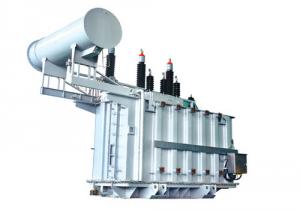
Brief Introduction
JDCF-138GYW is a product which have 4 windings and oil insulation voltage transformer.The product conform to the follows national requirement:GB1207-1997 phase <voltage transformer>,GB7354-85<Transofrmer Measurement of Partial Discharge>,GB311.1.19 <Insulation Coordination of High Voltage Transformation>,the international electric stand IEC186 or IEC60044 phase <Voltage Transformer> .This type product is used for electric energy measurement and relay protection in 145KV power system.
1.2 Structural characteristics
This type of voltage product has a cascading insulation structure.Iron corn is the " "shape and overlying by silicon steel sheet.Two iron corn were supported by shelf which mad by low dielectric phonetic paper board.Four coil nest is in the two iron com,The coil reelwith balance winding.measuring secondary winding,protective secondary winding,residual voltage winding.The primary winding was made by unifilar enameled wire and have four class,The upper extreme(A extreme) is all insulation.The lower extreme(N extreme)joint to expansion equipment plinth by push ring.There are three oil mark(+45oC,+20oC,-25oC) beside the expansion equipment.The plinth support the whole product,the terminal of measuring secondary winding,protective secondary winding,residual voltage winding,primary winding bring out formthe plinth.The primary winding N extreme joint to the plinth by joint panel which will be convenient to the test and installation.
1.3 Product mark
the primary winding is A and N,the measuring secondary winding is 1a,1n.the proctive secondary winding is 2a,2n.the residual voltage winding is da,dn.
Type description 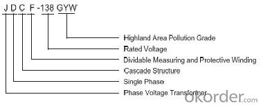
Operation condition
2.1 Am bient temperature:
maximum air temperature:+45oC
minimum air temperature:-25oC
maximum average air temperature:+30oC
2.2 altitude:≤3000m
2.3 minimum creepage distance:3520mm
2.4 atmosphere condition:have o serious pollution in atmosphere,the pollution grade is Ⅲ.
2.5 earthing manner:neutral point joint the earthing efficiently.
The rated value and requirement
3.1 the rated voltage
a.the maximum voltage:145kv
b.the rated primary voltage:138000/V
c.the rated voltage of measuring and protective winding:115/V
d.the rated voltage of residual voltage winding:115V
3.2 the rated frequency:50HZ
3.3 phase:single phase
Operation and maintenance
4.1 Before the installation,inspect the sealed place and welding.It has oil leakage and oil surface is normal,If not,it should oiling the same type oil.
4.2 The oil drawing is from the bottom and its electric intensity is not more than 50KV
4.3 The secondary should not open circuit in the product operation.
4.4 The product should veiled when it storage Before the operatio,it should not be sun or rain.The product shoue be packed.
No tesdge for ordering
a.type of product
b.the rated voltage of each winding
c.accuracy class and rated load
d.Frequency 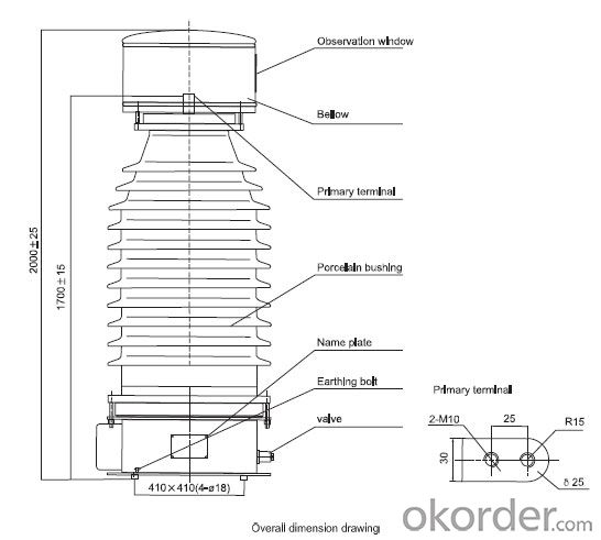
- Q: Electrical Machinery, electrical machines, transformers
- A transformer steel core's remanence means that it retains a static magnetic field when power is removed. When power is then reapplied, the residual field will cause a high inrush current until the effect of the remanent magnetism is reduced, usually after a few cycles of the applied alternating current. Overcurrent protection devices such as fuses must be selected to allow this harmless inrush to pass. When a transformer is livened, the magnetizing inrush currents are estimated as multiples of the transformer's nameplate kVA. Time Current (sec) - (amps) 0.01 -- 25x 0.10 -- 12x In addition, during the normal life of a transformer you can expect hot-load and cold-load pick-up events. These are estimated as Time Current 1.00 -- 6x 10.0 -- 3x 100. -- 2x You must select transformer fusing that will not be damaged by these events. Drop me an e-mail for a more detailed explanation.
- Q: I got stuck in a problem while solving the previous exam question for my courseTwo transformers with unequal turn ratio and unequal ratings are connected in parallel and have the same secondary voltage. How will the load be distributed between them? Hence find the circulating current.I know how to find the circulating current when the secondary voltages are different. But how can there be a circulating current if the secondary voltage is same?And I know about the load distribution being inversely proportional to the line impedance of the transformers, but what will be the change taking circulating current into account?
- That you may put both the transformers on the same line on their essential aspects however they must have different hundreds at their out places. You ought to use a small load on a 200kva and better load on 500kva. For higher guidance are attempting reffering an electrical engineer near you. I am also an electrical engineer.
- Q: i am going to the mall and getting a target transformers pc game!anyone want to tell me about it?or anything i need to know or any cheats you can give me
- Download: okorder
- Q: Current and Potential transformers both are actually Instrument transformers, which step down or lower down the values of current and voltages for measuring purposes.But I have heard of that both CT and PT specifically are used for stepping up current and voltages at some point of transmission system.if this is correct then can anyone tell where they are used?If not then there are step up transformers for similar uses but my question is why they are not called as CT's or PT's.
- Assume the source is our normal house electric supply. Assume that the following loads will work safely for the two voltages. Case 1. The load is impedence type. Then Power is Voltage^2/impedence. Example is our heater load. Hence by manupulation of the impedence, we can manupulate the power output. Case 2. Assume it is a constant horse power motor load similar to our fridge. Adjustment of voltage will not alter the power output. The power output will be entirely decided by the load horse power. But an increase voltage will reduce the input current, there by reducing the heat loss in the load.
- Q: Before engaging any technician i want to gather some knowledge about planer transformer. It will be good if u have any suggestions.
- In the planar transformers, the winding is done on flat conductive guide line of printed-circuit board printed circuit board or directly the copper mooring. Flat geometry reduce loss of skin effect when switching frequency is high, that is the eddy current loss. Therefore, effectively use the surface conductivity of copper conductor, much higher efficiency than conventional transformers. A profile map of flat transformer, and make use of the different distance between two windings, to obtained leakage inductance and impedance values under the different gap 5vdc 1a adapter.
- Q: I am learning about transformers and one of the items to calculate is the impedance. I need to calculate regular 60 Hz Core and Coil Shell Type Transformers Al wire in secundary, Cu Wire primary and use Epoxy paper for insulation.
- It's pretty difficult to calculate the impedances (there's more than one) entirely from the transformer's design data. It's easier and more usual to decide on an equivalent circuit (there are plenty available depending on how well you want to model the transformer) and then to determine the parameters by a mix of calculation and measurement. A pretty basic equivalent circuit which refers all impedances to the primary side, has the primary terminals connected first by Xm and Rc in parallel (the magnetising reactance and core loss resistance) and then by a third parallel branch containg a series connection of leakage reactance Xl, winding resistance Rw and an ideal transformer of turns ratio Np/Ns. Xm is best obtained from an open circuit test but could be calculated as the inductance of the primary winding. For the latter you'd need to know core dimensions, number of winding turns and the magnetising characteristic of the core iron. If you have conductor sizes and conductivities you can calculate the winding resistance Rw, referring the secondary part to the primary by multiplying it by (Np/Ns)?. You can deduce Rc from the losses measured on open circuit at nominal voltage and Rw from dc resistance measurements on the windings. If you know the specific hysteresis and eddy current losses of the core material, you can also have a good stab at calculating Rc. The leakage reactance is quite difficult to calculate from first principles - even designers usually resort to some empirical factors. Basically it's determined from the short circiut test which is at nominal secondary current. The ratio of primary volts to secondary surrent (referred of course) on secondary short circuit will get you close to Xl - you can adjust for Rw which can be determined from the losses on short circuit (core losses are absent here!) or by the two methods indicated above. It's normally Xl that's referred to as the transformer reactance and together with Rc and Rw, the impedance.
- Q: hi can anyone tell me when installing/replacing a door bell transformer when switching off power supply at main source will that make it safe to work with the connections, it keeps telling us to turn fuses off well it dont have fuses its a circuit breaker. so do we turn circuit breaker off asweel as main supply into house. may be a silly question to ask but dont wnat any trips to A nad E lol thanks guys xxx
- Years ago 25+ Friedland bell transformers had two glass fuses 0.5amp,these very small glass fuses protected the transformer windings.These could be the fuses they are referring to,the main supply,as you have pointed out is fed from your circuit board. Isolate that breaker and remove the cover on your transformer and have a look for your fuses,these glass fuses are about half an inch long.Hope you are successful.
- Q: Can a transformer be used with dc? what happens is a transformer designed for 120v ac is connected to a 120 v dc line?
- No, it can't. If it is connected to 120VDC, the output will give an initial pulse that decays to zero and stays there. The input will draw far more current than designed, overheat, and either open up or catch on fire. Here is how a transformer works with AC: The input winding generates a magnetic field (because it is an electromagnet). The field alternates because the applied current alternates. The alternating magnetic field couples into the output winding where it induces an electric voltage that alternates because the magnetic field is alternating. Now here's the kicker. The voltage induced in the output winding is proportional to the rate of change of the fluctuating magnetic field. If the field is static (ie, steady, as is the case if the input winding is powered by DC), then the rate of change is zero and the induced voltage is zero. That's why the transformer can't transform DC. Other interesting facts: The input winding converts electrical energy into energy in the magnetic field that is then converted back into electrical energy in the output winding. The input winding resists DC current based on the winding's resistance. If the input current is alternating, then it resists the current additionally based on the inductance of the winding, and the higher the frequency, the more it resists. A transformer is designed to work on a specific frequency (eg, 50Hz or 60Hz). Operating it at 0Hz (DC) will allow too much current to flow. The higher the applied frequency, the more power the transformer can transfer. Think of it as though the transformer passes a bucket of energy from input to output on each cycle. The more cycles per second, the more energy per second, aka the more power. At 0Hz (DC), it isn't passing any buckets of energy. Hope that helps.
- Q: Can somebody please help me understand this problem and help me do it? I'm having a hard time with it and help would be greatly appreciated.The following test data were obtained from short-circuit and open-circuit tests of a 50-kVA, 2400-600 V, 60Hz transformer.Voc600V Vsc76.4 VIoc3.34 A Isc 20.8 APoc 484 W Psc 754 WDetermine:A) the equivalent high-side parameters;B) RegulationC)efficiency at rated load and .92 power-factor for lagging.
- read material regarding transformers Not just once but say 5 times, till you understand what is said. the transformer has copper loss due resistance of primary and secondary. It has additionally iron loss. The equivalent circuit is a sort of representation that brings in these losses. generally you can apply a low voltage to primary till shorted secondary has a current equal to less than rated current. These measurement details are given. Similarly open circuit measurement details are available. With understanding of how the rest can be calculated using worked examples in texts, you can solve it yourself. attempt this See Lee's book on transformers or schaums series on electrical engg.
- Q: What are the serious consequences of transformer circulation?
- In a three-phase power system, the three-phase voltage (or current) at the same time is the position of the phase, usually symmetrical balance of the three-phase voltage or current phase of the phase check 120 °, in the power system, generators and transformers Whether the phase is consistent, directly related to whether they can run side by side, and then the electromagnetic connection of the same system side by side or two transformers side by side, and the new line when the measurement phase is indispensable one of the experimental project, the purpose of the measurement is to determine the phase and Whether the phase sequence is correct, to prevent the phase and phase sequence from each other, in parallel with the short circuit or a huge circulation caused by burning equipment.
Send your message to us
JDCF-138GYW Phase Voltage Transformer
- Ref Price:
-
- Loading Port:
- Shanghai
- Payment Terms:
- TT OR LC
- Min Order Qty:
- -
- Supply Capability:
- 1000sets set/month
OKorder Service Pledge
OKorder Financial Service
Similar products


Hot products


Hot Searches
Related keywords

