
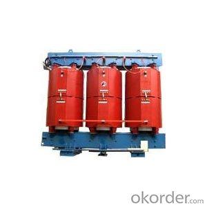
SH15-M Amorphous Alloy Oil-immersed Transformer
- Ref Price:
-

- Loading Port:
- China Main Port
- Payment Terms:
- TT OR LC
- Min Order Qty:
- -
- Supply Capability:
- -
OKorder Service Pledge
OKorder Financial Service
You Might Also Like


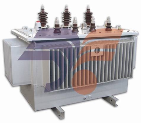
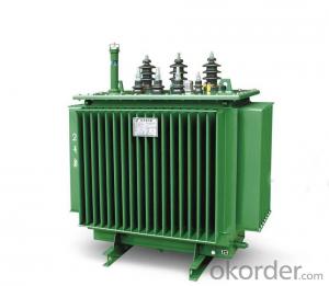
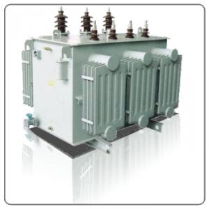
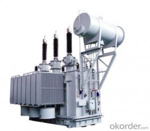
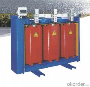
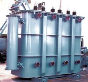
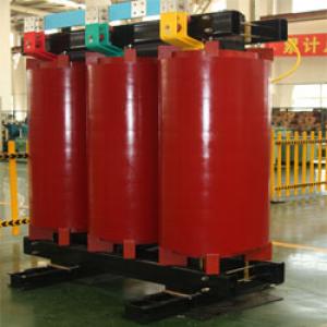
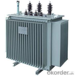
SH15-M Series
Amorphous Alloy Oil-immersed Transformer

Introduction of Products
Amorphous alloy isderived from iron, boron and other elements which rapid cooling down to mouldin order to arrange its atoms disordered. Compared with silicon sheets, the permeabilityof amorphous alloy is high, the no-load losses and current is lower, and moreoperation charges can be saved. Meanwhile, its heat is low,and it has good stability to make its working lifelonger.
Performance Characteristics
1. Saving power: The no-load losses reduce byabout 80% than that of S9 series.
2. Reliable: The capability of anti-shortcircuit is strong.
3. Protecting environment: Its noise is lowand it can decrease the discharging quantity of carbon.
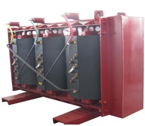
Structure Characteristics
1. The core adopts three-phase five-limb and HV winding adopts D connection,which eliminates the three fluxes and three-harmonic electric potential anddecrease eddy current loss and temperature caused by leakage. Meanwhile, the steepnessof impulse voltage is reduced.
2. The coil takesthe shape of rectangular, and use conductor tensioning device to wind. Itadopts shaping, press mounting and other technique measures to make the outsidedimension of coil come to design requirement. And that HV coils wind outside LVcoils improve the strength of coil and the capability of anti-short circuit.
3. There is no oilstorage tank and moisture absorber on the oil tank. The transformer oil doesn’tcontact with the air and the expansion of oil depends on the elasticity of corrugatedplates to compensate. This can eliminate maintenance and improve working life.
Normal Using Condition
1. The altitude is not more than 1000m.
2. Environment temperature
Highest temperature: +40℃
Hottest monthly average temperature: +30℃
Highest yearly average temperature: +20℃
Lowest temperature: -40℃
3. Using outdoors( or indoors)
4. The wave shape of supply voltage is approximateto sine wave.
5. The supply voltage of three phases isgenerally symmetric.
If thetransformers need to be used at abnormal condition, the details should beoffered when the users order.
Main Specification and Technology Parameter
1. Range of rated capacity: 50~2500kVA
2. Rated voltage: not more than 10kv
3. Rated frequency: 50Hz
4. Insulating level
Voltage Grade (kv) | The highest voltage effective value of equipment(kv) | Rated short-time applied withstand voltage(kV/min) | Rated lightning impact withstand voltage(peak)(kv) |
≤1 | 1.1 | 3 | -- |
6 | 7.2 | 20 | 60 |
10 | 12 | 35 | 75 |
5. The insulating classof transformer is A, coil temperature rise is not more than 65K, and thetemperature rise of top oil is not more than 60K.
6. Thetransformers correspond with the following standards:
a. GB1094.1~2, GB1094.3, GB1094.5 Power transformer
b. JB/T 10318 Technology parameter and request of oil-immersedamorphous alloy core distribution transformer
c. Standard of InternationalElectro-technical Commission: IEC60076, Power transformer
d. Q/SIHG1 SH15-M Technology parameter andrequest of three-phase oil-immersed distribution transformer of amorphous alloycore sealed type
7. TechnologyParameter of SH15-M Series
Rated capacity (kVA) | Voltage and tapping range | Symbol of connecting group | No-load losses (W) | Load losses (W) | No-load current (%) | Impedance of short circuit (%) | ||
HV(KV) | Tapping range (%) | LV(kV) | ||||||
30 |
6 6.3 10 10.5 11 |
±5 ±2x2.5 |
0.4 |
Dyn11 | 33 | 630 | 1.7 |
4 |
50 | 43 | 910 | 1.3 | |||||
63 | 50 | 1090 | 1.2 | |||||
80 | 60 | 1310 | 1.1 | |||||
100 | 75 | 1580 | 1 | |||||
125 | 85 | 1890 | 0.9 | |||||
160 | 100 | 2310 | 0.7 | |||||
200 | 120 | 2730 | 0.7 | |||||
250 | 140 | 3200 | 0.7 | |||||
315 | 170 | 3830 | 0.5 | |||||
400 | 200 | 4520 | 0.5 | |||||
500 | 240 | 5410 | 0.5 | |||||
630 | 320 | 6200 | 0.3 |
4.5 | ||||
800 | 380 | 7500 | 0.3 | |||||
1000 | 450 | 10300 | 0.3 | |||||
1250 | 530 | 12000 | 0.2 | |||||
1600 | 630 | 14500 | 0.2 | |||||
2000 | 750 | 17400 | 0.2 |
5 | ||||
2500 | 900 | 20200 | 0.2 | |||||
Outline Dimension
Type | Outside dimension (mm) | Weight (kg) | |||
Length | Width | Height | Oil weight | Total weight | |
SH15-30 | 1100 | 690 | 1090 | 130 | 630 |
SH15-50 | 1190 | 750 | 1140 | 160 | 710 |
SH15-63 | 1250 | 750 | 1160 | 160 | 750 |
SH15-80 | 1290 | 750 | 1200 | 170 | 810 |
SH15-100 | 1260 | 800 | 1190 | 180 | 870 |
SH15-125 | 1320 | 810 | 1220 | 190 | 940 |
SH15-160 | 1370 | 810 | 1220 | 210 | 1050 |
SH15-200 | 1410 | 800 | 1320 | 230 | 1140 |
SH15-250 | 1490 | 810 | 1360 | 260 | 1290 |
S(B)H15-315 | 1520 | 790 | 1430 | 280 | 1500 |
S(B)H15-400 | 1670 | 820 | 1510 | 330 | 1710 |
S(B)H15-500 | 1650 | 910 | 1450 | 370 | 1960 |
SBH15-630 | 1830 | 920 | 1440 | 430 | 2250 |
SBH15-800 | 1910 | 950 | 1500 | 480 | 2730 |
SBH15-1000 | 2000 | 1100 | 1490 | 620 | 3330 |
SBH15-1250 | 2100 | 1100 | 1580 | 730 | 3560 |
S(B)H15-1600 | 2120 | 1240 | 1560 | 860 | 3830 |
A comparison about no-load losses of amorphous alloyand silicon sheet
Capacity (KVA) | No-load losses (w) | |
S9 type (silicon sheet) | SHI5 type (amorphous alloy) | |
100 | 290 | 75 |
315 | 670 | 170 |
500 | 960 | 240 |
The Manufacturing Process of Amorphous Alloy Materials
a. The raw materials melt in the induction furnace.
b. The melted materials are transferred to feedingpart.
c. Control of casting head
d. After melting to be thin, it is sprayed to coolingwheel.
e. The sprayed materials cool down at the speed of 106℃ per second to form amorphous alloybelt.
f. Measure the width and thickness of alloy belt andfeedback to control system.
g. It is led to pull through unit.
h. Material receiving
A comparison to manufacturingprocess of amorphous alloy and silicon sheet
Amorphous alloy material Orientation silicon sheet

Social and Economic Effects
The manufacturingprocess of core materials of amorphous alloy core transformers is simple, andthe energy source losses are little, so the carbon discharge can be reduced.
No load losses are low, and the increased investment cost of transformers can be taken back within5 years.
Low operation temperature, small insulation deterioration, long working life.
The ordering basic data
1、Rated capacitance;
2、Rated voltage;
3、Rated frequency;
4、Tapping range;
5、Impedance voltage;
6、Using condition;
7、Other performance data should be indicated inthe contract.
- Q: A transformer is a two coil component that uses electromagnetic induction to pass an AC signal from its input to its output.?How and why are transformers used on electric wires? What would be their purpose??Why do we hear that these transformers break at times?
- 1. Transformers are used to step up (or step down) AC voltage/current. Further, they can provide electrical isolation from two circuits (There is no physical connection between the two sides of a transformer). 2. Transformers can break for a lot of reasons, i.e. excessive heat, too large of a load, environmental breakdown, faulty manufacturing, etc
- Q: I need a flyback transformer for some plasmatastic experiments. I know a place where someone dumped a bunch of broken TVs and computer monitors. Where should I be looking for a flyback transformer in this stuff and what can it look like?thanks
- Whatever okorder
- Q: Can a transformer having a given VA rating at 50Hz handle more power at a higher frequency, say, 300Hz or 400Hz?I want to build an inverter to run an 11 watt compact fluorescent lamp. Since these devices rectify the supply directly, there does not seem to be any good reason to feed the lamp with 50Hz.If my understanding is correct, the core has to be able to store up to one half-cycle's worth of energy in the magnetic field (which will then be released out of the secondary winding in the form of electricity) to avoid going into saturation and overheating. So at twice the frequency, it should be possible to push twice as much power through for the shorter half-period without saturating the core. (Actually, probably a little less than twice as much, as there will be more resistive heating; but transformer wire is often slightly thicker than it really needs to be, just because it's less likely to break in the winding machine.)So can I over-run a transformer this way, or is there some gotcha that I've missed?
- The equation V 4.44fNaB determines what is required for a transformer to avoid saturation. V is the voltage, f is the frequency, N is the number of turns of wire in the winding, a is the area of the core, and B is the peak magnetic flux density. The transformer has presumably been designed so that the peak flux density is as high as it can be without saturating the core. For an existing transformer, V/f a constant. If you increase f, you can increase V so that V/f remains constant. However, the hysteresis losses increase in proportion to the frequency increase and the eddy current losses increase in proportion to frequency squared. In addition, skin effect will increase the copper losses at higher frequencies. Reducing the copper losses by reducing the current would compensate for the skin effect. Reducing the copper losses would tend to compensate for the increased iron losses, but it is hard to say how much a cooler coil will compensate for a hotter core.
- Q: does anyone have the trailer for transformers
- No there is no trailer yet because there is no footage yet. The film is currently 'in production' and will hit cinemas next year. Look for a teaser soon enough.
- Q: Do you think if I asked this. which I am maybe people will pick Transformers because more Americans watch Trans instead of Gundam but if people watched both, would they still pick Transformers?
- What, in a battle or as in an anime? If it's anime, I pick Gundam. If it's a battle. Well Transformers got someone called Unicorn who's the size of a Planet. So you can imagine how powerful he is.
- Q: does anyone know what the songs are in transformers???????
- 01. Linkin Park - What I've Done 02. Smashing Pumpkins - Doomsday Clock 03. Disturbed - This Moment 04. Goo Goo Dolls - Before It's Too Late (Sam and Mikaela's Theme) 05. The Used - Pretty Handsome Awkward 06. HIM - Passion's Killing Floor 07. Taking Back Sunday - What It Feels Like To Be A Ghost 08. Styles of Beyond - Second 2 None (feat. Mike Shinoda) 09. Armor For Sleep - End of the World 10. Idiot Pilot - Retina and the Sky 11. Julien-K - Technical Difficulties 12. Mutemath - Transformers Theme
- Q: I personally thought transformers was worse but very similar to the avengers.
- They're both excellent movies - 10/10 but I prefer Transformers. I even find the Transformers games more fun than the Marvel (Superhero) games edit: I also agree with Uxielixe, the music is great. I learned a lot of Transformers music on piano and electric guitar.simply beautiful and I love Iron man in The Avengers.
- Q: I just saw the mythbusters use a neon transformer to spark a methane explosion and the arch looked like a continuous irredecent light. So are neon transformers a part of neon lights? That and if you know, what is the inert gass inside the lights?
- Neon transformer just an ordinary step up transformer to produce 5000V at very low current (a few mA) Neon light is a long tube fills with neon gas.
- Q: I use a 1000 watt transformer for my tv, dvd player, cd player, game cube and nintendo (only 2 can be plugged in at a time or it is a fire hazard). The transformer is very strong and flips the circuit breaker if anything else in the house is plugged in and I try to plug that in. I'd rather not have to unplug everything to plug it in but I am worried I am wasting electricity if I keep it plugged in. So my question is does transformers use energy if they are plugged in and the appliances plugged into it aren't turned on? Also, do you think I can use a smaller transformer for those items listed above if it does use energy? The boxes that I buy them in don't say, they just say what watt they are.I've tried to look it up but I can't understand any of it so thank you in advance for helping me.
- Any transformer will use electricity when the device is not turned oncell phone chargers are the most common. A transformer or is just a coil of wire going from one prong to the other in that plug.
- Q: What is the meaning of the transformer 'turns ratio'? what's the effect?
- The turns ratio of the transformer is the ratio of the transformer, that is, the ratio of the turns of the original coil and the secondary coil. Role: reflects the original transformer, vice coil voltage RMS ratio. In the case where the no-load current is negligible, the magnitude of the original and secondary coil current is inversely proportional to the number of turns. For example, 220 volts to 10 volts voltage ratio is 220: 10, turns ratio should also be 220: 10, such as the primary is 2200 laps, the secondary should be 100 laps. Multi-turn ratio is the number of turns of the secondary output and the primary correspondence. A variety of turns ratio is to allow a sensor device is used for a variety of heat treatment process. Transformer is the use of electromagnetic induction principle to change the AC voltage of the device, the main components are primary coil, secondary coil and core. The main functions are: voltage conversion, current conversion, impedance conversion, isolation, regulation (etc., according to the use can be divided into: distribution transformers, power transformers, sealed transformers, modular transformers, dry transformers, Single-phase transformers, electric furnace transformers, rectifier transformers, etc. Transformers are the use of electromagnetic induction principle to change the AC voltage device, the main components are primary coil, secondary coil and core. The main functions are: voltage conversion, current conversion, , Isolated, regulated (etc.) by use can be divided into: power transformers and special transformers. Circuit symbols commonly used as the beginning of the number. Example: T01, T201 and so on.
Send your message to us
SH15-M Amorphous Alloy Oil-immersed Transformer
- Ref Price:
-
- Loading Port:
- China Main Port
- Payment Terms:
- TT OR LC
- Min Order Qty:
- -
- Supply Capability:
- -
OKorder Service Pledge
OKorder Financial Service
Similar products
Hot products

Hot Searches
Related keywords

