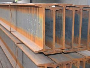


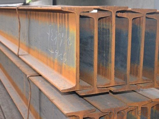
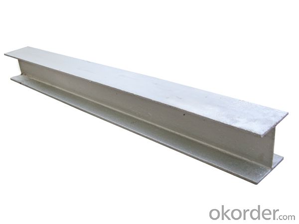
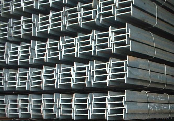
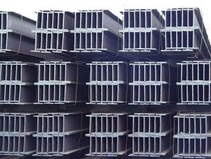
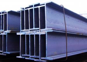
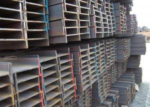
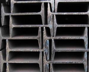
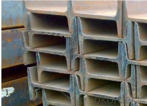
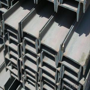
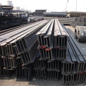
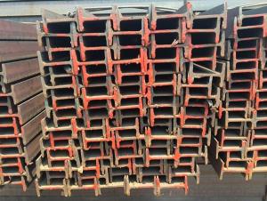
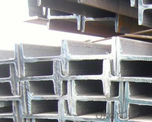
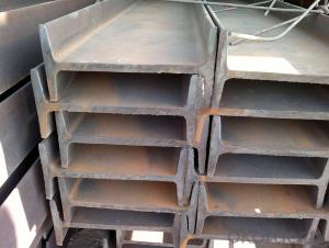
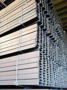
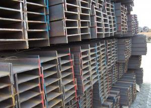
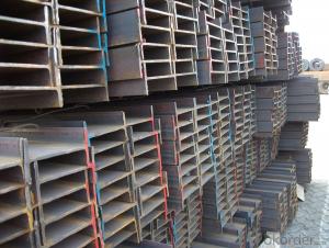
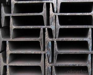
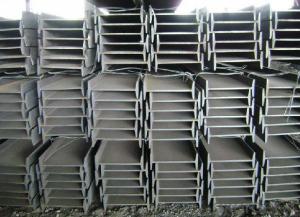
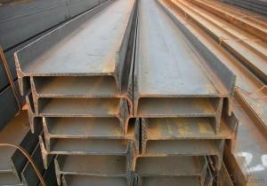
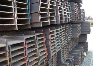
IPEAA 100 stainless steel I-Beam for construction EN10025
- Ref Price:
-

- Loading Port:
- Tianjin
- Payment Terms:
- TT or LC
- Min Order Qty:
- 25 m.t.
- Supply Capability:
- 100000 m.t./month
OKorder Service Pledge
OKorder Financial Service
You Might Also Like
Product Description:
OKorder is offering IPEAA 100 stainless steel I-Beam for construction EN10025 at great prices with worldwide shipping. Our supplier is a world-class manufacturer of steel, with our products utilized the world over. OKorder annually supplies products to European, North American and Asian markets. We provide quotations within 24 hours of receiving an inquiry and guarantee competitive prices.
Product Applications:
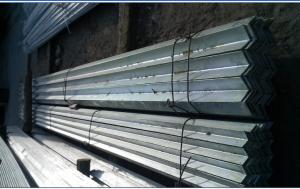
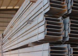
IPEAA 100 stainless steel I-Beam are ideal for structural applications and are widely used in the construction of buildings and bridges, and the manufacturing, petrochemical, and transportation industries.
Product Advantages:
OKorder's Steel I-Beams are durable, strong, and resist corrosion.
Main Product Features:
· Premium quality
· Prompt delivery & seaworthy packing (30 days after receiving deposit)
· Corrosion resistance
· Can be recycled and reused
· Mill test certification
· Professional Service
· Competitive pricing
Product Specifications:
Specifications
1. Invoicing on theoretical weight or actual weight as customer request
2. Standard: EN10025, GB Standard, ASTM
3. Grade: Q235B, Q345B, SS400, ASTM A36, S235JR, S275JR
4. Length: 5.8M, 6M, 9M, 12M as following table
5. Sizes: 80mm-270mm
Appications
1. Supporting members, most commonly in the house raising industry to strengthen timber bears under houses. Transmission line towers, etc
2. Prefabricated structure
3. Medium scale bridges
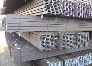
4. It is widely used in various building structures and engineering structures such as roof beams, bridges, transmission towers, hoisting machinery and transport machinery, ships, industrial furnaces, reaction tower, container frame and warehouse etc.
Package & Delivery
1. Packing: it is nude packed in bundles by steel wire rod
2. Bundle weight: not more than 3.5MT for bulk vessel; less than 3 MT for container load
3. Marks: Color marking: There will be color marking on both end of the bundle for the cargo delivered by bulk vessel. That makes it easily to distinguish at the destination port.
4. Tag mark: there will be tag mark tied up on the bundles. The information usually including supplier logo and name, product name, made in China, shipping marks and other information request by the customer.
If loading by container the marking is not needed, but we will prepare it as customer request.
5. Transportation: the goods are delivered by truck from mill to loading port, the maximum quantity can be loaded is around 40MTs by each truck. If the order quantity cannot reach the full truck loaded, the transportation cost per ton will be little higher than full load.
6. Delivery of IPE Beam: 30 days after getting L/C Original at sight or T/T in advance
Production flow
Material prepare (billet) —heat up—rough rolling—precision rolling—cooling—packing—storage and transportation


FAQ:
Q1: Why buy Materials & Equipment from OKorder.com?
A1: All products offered byOKorder.com are carefully selected from China's most reliable manufacturing enterprises. Through its ISO certifications, OKorder.com adheres to the highest standards and a commitment to supply chain safety and customer satisfaction.
Q2: How do we guarantee the quality of our products?
A2: We have established an advanced quality management system which conducts strict quality tests at every step, from raw materials to the final product. At the same time, we provide extensive follow-up service assurances as required.
- Q: Can steel I-beams be used in stadiums or arenas?
- Yes, steel I-beams are commonly used in the construction of stadiums and arenas. They provide strength and structural support necessary for large-scale buildings, allowing for wide open spaces and long spans without the need for excessive columns or supports.
- Q: What are the different connection methods for Steel I-Beams?
- There are several different connection methods for Steel I-Beams, depending on the specific application and structural requirements. Some of the common connection methods include: 1. Welding: This is the most common method used to connect steel I-beams. It involves melting the base metal and applying a filler material to create a strong joint. Welding provides excellent strength and rigidity, making it suitable for heavy-duty applications. 2. Bolting: Bolts can be used to connect steel I-beams together. This method involves drilling holes in the flanges or web of the I-beams and inserting bolts through these holes, along with washers and nuts, to tighten and secure the connection. Bolting provides ease of installation and disassembly, making it suitable for temporary or adjustable structures. 3. Riveting: Rivets are another traditional method of connecting steel I-beams. This process involves inserting a rivet through pre-drilled holes in the flanges or web of the I-beams and then deforming the rivet to create a permanent connection. Riveting provides high strength and reliability but requires specialized tools and expertise. 4. Adhesive bonding: In some cases, adhesive bonding can be used to connect steel I-beams. This method involves applying a high-strength adhesive to the surfaces of the I-beams and then pressing them together to create a bond. Adhesive bonding can provide a clean and aesthetically pleasing connection, but it may not be suitable for heavy loads or dynamic loads. 5. Mechanical connectors: There are various mechanical connectors available in the market specifically designed for connecting steel I-beams. These connectors are often prefabricated and can be easily installed by bolting or welding. They provide a quick and efficient method of connecting I-beams while maintaining high strength and load-bearing capacity. It is important to consider the specific structural requirements, load conditions, and design constraints when selecting the appropriate connection method for steel I-beams. Consulting with a structural engineer or a qualified professional is recommended to ensure the chosen connection method meets the necessary standards and specifications.
- Q: How are steel I-beams repaired if damaged?
- Typically, when steel I-beams are damaged, they undergo a specific set of steps for repair. Firstly, the extent of the damage is assessed by a trained professional who examines the beam to determine its severity and location. Once the assessment is complete, the next step involves stabilizing the beam. This is achieved by utilizing temporary supports or braces, which ensure the beam's security and prevent a collapse during the repair process. This step is crucial for worker safety and to prevent further damage. Following stabilization, the damaged section must be removed. This is typically accomplished by cutting out the affected portion of the beam using tools like torches or saws. It is imperative that all damaged material is eliminated to guarantee a proper repair. With the damaged section removed, a new piece of steel is usually fabricated to replace it. The replacement piece is then meticulously welded or bolted into place using specialized techniques and equipment. The welding process is vital to ensure a durable and robust repair. After securely attaching the new section, the repaired I-beam is often subjected to inspection to verify the quality of the repair. Non-destructive testing methods like ultrasound or x-ray may be employed to identify any potential defects or weaknesses. Finally, if necessary, the repaired I-beam may undergo painting or treatment to safeguard it against corrosion and prolong its lifespan. In conclusion, the process of repairing a damaged steel I-beam entails assessing the damage, stabilizing the beam, removing the damaged section, fabricating and attaching a new section, inspecting the repair, and potentially painting or treating the beam. This process necessitates skilled professionals and specialized equipment to ensure a safe and effective repair.
- Q: How do steel I-beams resist fire?
- The resistance of fire by Steel I-beams is due to their inherent properties and design features. To begin with, steel possesses a higher melting point in comparison to other construction materials such as wood or concrete. This characteristic allows steel to endure higher temperatures before it starts to weaken or lose its structural integrity. In the case of I-beams, their shape enables an increased surface area, which aids in the efficient dissipation of heat and hinders the rapid spread of fire. Furthermore, steel is a material that does not combust, meaning it does not contribute to the fuel load of a fire. This attribute is crucial for fire safety as it prevents the fire from spreading or intensifying in the vicinity of the I-beams. Moreover, various fire-resistant coatings or fireproofing materials can be applied to protect steel I-beams. These coatings are specifically designed to insulate the steel from high temperatures and fire exposure. They act as a barrier, impeding the transfer of heat to the steel and prolonging the time it takes for the beams to reach critical temperatures. In addition, when designing steel I-beams, fire safety measures are often taken into consideration. These beams are engineered to have sufficient load-bearing capacity even in the event of a fire. This is achieved through measures such as incorporating additional redundancy, including fire protection systems, and employing structural strategies that minimize the impact of thermal expansion. In summary, steel I-beams resist fire due to their high melting point, non-combustible nature, the application of fire-resistant coatings or fireproofing materials, and their consideration of fire safety in their design. These factors work together to ensure that steel I-beams maintain their strength and integrity during a fire, thus enhancing fire safety in buildings and structures.
- Q: How do steel I-beams perform in areas with high salinity or corrosive environments?
- Steel I-beams perform relatively well in areas with high salinity or corrosive environments due to their inherent corrosion resistance. The iron in steel naturally reacts with oxygen and moisture in the air to form iron oxide (rust), which acts as a protective barrier against further corrosion. Additionally, steel I-beams can be further protected through coatings or galvanization processes, which provide an extra layer of defense against corrosive elements. However, prolonged exposure to extreme levels of salinity or corrosive substances may eventually compromise the steel's integrity, requiring regular maintenance and inspections to ensure their long-term performance in such environments.
- Q: Can steel I-beams be used for overhead crane support?
- Yes, steel I-beams can be used for overhead crane support. They are commonly used in the construction industry for their strength and load-bearing capabilities, making them suitable for supporting the weight of an overhead crane.
- Q: How are steel I-beams classified?
- Steel I-beams are classified based on their dimensions, specifically their depth (or height), width, and weight per foot. The classification is typically denoted by a series of numbers and letters that represent these dimensions, such as "S" for standard beams or "W" for wide flange beams, followed by the dimensions in inches. For example, a W10x22 beam would have a depth of 10 inches and weigh 22 pounds per foot.
- Q: What is the weight range of steel I-beams?
- The weight of steel I-beams can differ depending on their dimensions and length. Nevertheless, as a general rule, smaller beams typically weigh around 6 pounds per foot (8.9 kilograms per meter), while larger and heavier beams can go up to 260 pounds per foot (386 kilograms per meter). It should be noted that these weight ranges are approximate and subject to variation based on the specific grade and type of steel used in the I-beam's construction. Furthermore, any additional modifications or features, like holes or cut-outs, can impact the beam's weight by reducing it.
- Q: Can steel I-beams be used in the construction of amusement parks and entertainment venues?
- Yes, steel I-beams can be used in the construction of amusement parks and entertainment venues. Steel I-beams are commonly used in the construction industry for their strength, durability, and load-bearing capabilities, making them suitable for supporting large structures and attractions found in amusement parks and entertainment venues.
- Q: Are steel I-beams prone to corrosion?
- Yes, steel I-beams are prone to corrosion if they are not properly protected or coated.
Send your message to us
IPEAA 100 stainless steel I-Beam for construction EN10025
- Ref Price:
-
- Loading Port:
- Tianjin
- Payment Terms:
- TT or LC
- Min Order Qty:
- 25 m.t.
- Supply Capability:
- 100000 m.t./month
OKorder Service Pledge
OKorder Financial Service
Similar products
Hot products
Hot Searches
Related keywords

