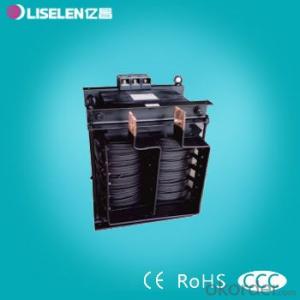


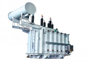
BK Transformer Variable Voltage Power supply
- Ref Price:
-

- Loading Port:
- Tianjin
- Payment Terms:
- TT OR LC
- Min Order Qty:
- 1 unit
- Supply Capability:
- 500 unit/month
OKorder Service Pledge
OKorder Financial Service
You Might Also Like


Products can be customized according to customer requirements!

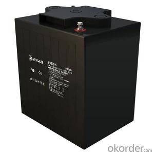
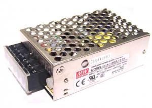
Applicable scope: suitable for 50Hz ~ 60Hz AC circuit, widely used in machine tools and mechanical equipment, such as driving, marine, wind power, photovoltaic power generation, testing machine, etc., general electric control power, local lighting and light power supply.

With good performance, reliable operation, low energy consumption, small size, wiring safety, applicability, etc., can work under the rated load, is a kind of ideal variable power supply.


Company have 21 years of business history, set research and development, production and sales as one of professional transformer manufacturing enterprises, also is transformer industry of Shandong Province CQC certification (the original Great Wall certification system, certification time longest enterprises (14 years), mainly produce and sell all kinds of transformer products, including: (transformer Division) three-phase dry type transformer, intelligent three-phase servo transformers, BK\JBK1\JBK3\JBK5 control transformer, toroidal transformer, (small transformer Division) pin, potting type, lead type power transformer series products. (high-frequency transformer Division) EE series, EFD series, PQ series, filter, I-inductor, loop inductance etc..
We are able to supply various types of terminal blocks according to clients' requirement,Please contact us so we can offer you the best quality,competitive price and timely delivery.
- Q:What is the SN on the transformer? What is the difference between it and the actual power of the transformer?
- The unit of apparent power SN is kVA, "Transformer's actual power" is said that active power, right? Active power PN = SN * power factor, in kW
- Q:I have been reading wikipedia and have gotten confused.Va.Number of Coils on side a---- ._________________Vb.Number of Coils on side bwikipedia mentioned how power companys use transformers for converting to high voltage power li nes then use transformers to bring the voltage back down.Focusing on the transformer that jacks the voltage upwirea-[side a-Transformerxyz- side b]-wirebso assum wireb is the high voltage power line.--Which side of transformerxyz would have more coils ? My guess is that side b has more coils then side a--Is it safe to say that the wattage of side a is equal to side b?--they said something about magnetic flux, does this just mean that the material connecting side a to side b has to be magnetic?--they said that the insulation wears down in transformers over time due to heat. what is causing this heat?--they said something about leakage and spacing of coils, what does this mean?tyVVVVVVVm
- The number of turns is proportional to the voltage on that side. So if you connect a voltage to the side with 100 turns, and the other side has 1000 turns, you will get out 10 times the voltage you put in. However, the current available is only 1/10 as much, so the output power is the same as the input power (wattsvolts*amps). To transfer power efficiently, especially at low frequencies, both coils of the transformer are wound around the same piece of magnetic material. All wire has some electrical resistance. When current flows through it, voltage is produced (voltsamps*ohms), and the combination of voltage and current produces heat. The wires making up the coils are covered with insulation, and there is insulation between the coil and the core, and between the two windings, but the voltages may be 100,000 volts or more, and this is enough to cause sparks between windings or from the windings to the frame if there is a spot with no insulation.
- Q:I use transformers in my circuitry all the time but when a transformer is say a secondary 12v 1a transformer than what does it mean by 1 ampis it that the secondary winding wire will pop after 1 amp doo to the simple thinness of the wire? or that the ohms of the secondary coil, when using iv/r, 112/12so does this tell you that the coil is 12 ohms?please don't give me other information about the transformer just answer the question please.
- It means the transformer secondary voltage is 12 volts and the current rating is 1 amp. If you put a higher current load on the transformer it won't pop, but it will overheat and the insulation will degrade faster than if the current was kept below 1 amp. If the current is allowed to go too high, the transformer will fail in a short time.
- Q:how could I describe the physics of transformer?
- A device by which you can increase or decrease the available AC mains voltage.
- Q:everyone's been fighting about if jazz from transformers is white or black i think he's just white pretending to be black what do you guys think
- Jazz is always voiced by an African American actor, Scatman Crothers, Darius McCrary, Phil Lamaar, but even though Transformers have varying ethnic voice actors, or for some reason, a human foreign accent, they're one race and not considered white or black, or foreign no matter what part of Cybertron they come from. They're either Autobot or Decepticon, and they're allegences, not races. They're Cybertronian by birth, Decepticon is a faction name created by Megatron, and Autobot is the governing force later changed to the title of the good guys amidst the war. I think it's just tradition for Jazz to have a African American voice and sound cool on acount of his name
- Q:A single phase transformer operates from a 230V supply. The primary and secondary resistances are 0.03 Ω and 1.12Ω respectively while the corresponding leakage reactances are 0.1Ω and 6.4Ω; the magnetising branch can be neglected. The secondary winding has four times as many turns as the primary. Calculate :i) The equivalent impedance referred to the primary circuitii) The secondary terminal voltage when the load has a resistance of 200Ω and an inductive reactance of 100Ω.iii) The secondary terminal voltage when the load has a resistance of 200Ω and a capacitive reactance of 100Ω.Can someone show me how to tackle this question please?
- i) the secondary transformer impedance is 1.12 + j6.4Ω. Since Ns/Np 4, this impedance reflected to the input is (1.12 +j6.4Ω)/(Np/Ns)? 007 + j0.4Ω ii) Reflect the primary transformer voltage and impedance to the secondary side. 230(Ns/Np) (1.12Ω + j6.4Ω + (Ns/Np)?(0.03Ω + j0.1Ω ) +200Ω + j100Ω )I 920 (1.6 +200 + j8 +j100)I (201.6 + j108)I |Z| 228.7Ω √(201.6? + 108?) at angle of inverse tan (108/201.6) 28.18° I 4.02 amps at -28.18° 3.54 - j1.90 amps The terminal voltage is 920 - (1.6Ω +j8Ω)(3.54 - j1.90 amps) iii) solve 920 (1.6Ω +200Ω + j8Ω - j100Ω)I (201.6Ω - j92Ω)I The terminal voltage is 920 - (1.6Ω + j8Ω)I
- Q:I have a power transformer and i forget where it came from. It has two leads from a wall outlet plug and then goes to the main (square) casing. there are three wires that come out the other side. They are from left to right, red,white and red. I assume its a 9v ac to dc transformer but am not positive. Can someone help me? I suspect that the white wire is ground. Any help would be great.
- There's no reason to assume anything, except that the primary side (with the line cord and plug) is probably intended for 115 Volts, AC. If it's a transformer (rather than a power supply) it's not AC to DC at any voltage. Transformers convert AC to AC. With those colors on the secondary, there's a pretty good chance it's center-tapped. Red-to-red will be twice the voltage of either red-to-white. Nothing should be grounded to the transformer case.
- Q:I assume that if i have a 1000 watt transformer, it is always using a thousand watts, just by being plugged in. So if I run a 1000 watt Japanese microwave on a 1000 watt transfornmer, then even when the microwave is not in use I am using a thousand watts right? The same as having a1000 watt heater going all the time. Of couse I can turn off the transformer, but that is a hassle.How, and if it is impossible-why?, can i convert a TV designed to run on 100v in japan to 240 V in New Zealand? or a fridge etc?
- The waste of energy comes primarily from inefficient standby features and excessive power consumption by the transformer when it has no load1. For example, a telephone charger left plugged in the wall will draw electricity even when the equipment is fully charged and is not in use. Such electricity waste is described as leaking electricity. Try to rent a transformer now if you want to save some dollars.
- Q:Hello forum,I have a question pertaining to transformers. I understand the current oscillating in a coil of wires around a toroid-type metal induces a moving magnetic field in the metal, which induces current in another set of coils on the other side, right? If I'm slightly correct, yay1) Are transformers specifically AC? Can there be DC transformers or would I have to rectify it after it's been stepped-down?2) Is the output voltage independent of the current? Let's say I have 50W, 120V stepped-up to 240V. If I change the power supply to 100W, will the voltage still be stepped up the same, while current would be twice as high? (Ideally)Thanks!
- Transformers can work on dc if you oscillate the pulse. a steady dc voltage will not produce the any inducement. a simple 555 timer will work on small dc voltages. for larger voltages you could actually use an on/off switch and switch it manually very fast. High voltage oscillators are available. But rectifying is not necessary
- Q:I have a 120v X 24v step down transformer that is capable of supplying 30 amperes. I need to convert the output to dc to supply a project I am working on. I have a bridge rectifier capable of handling 10 amps continuously, but nothing that could handle the 30 amp output. What would occur if I put the rectifier on the input side (with no filter capacitors) and fed the xfmr the DC voltage with 120hz ripple? I suspect the xfmr wont like the 120hz input and generate excessive heat. Anybody know for sure? The xfmr has a laminated iron core and copper windings.
- The transformer will not work correctly with pulsating DC. It will overheat.
1. Manufacturer Overview |
|
|---|---|
| Location | |
| Year Established | |
| Annual Output Value | |
| Main Markets | |
| Company Certifications | |
2. Manufacturer Certificates |
|
|---|---|
| a) Certification Name | |
| Range | |
| Reference | |
| Validity Period | |
3. Manufacturer Capability |
|
|---|---|
| a)Trade Capacity | |
| Nearest Port | |
| Export Percentage | |
| No.of Employees in Trade Department | |
| Language Spoken: | |
| b)Factory Information | |
| Factory Size: | |
| No. of Production Lines | |
| Contract Manufacturing | |
| Product Price Range | |
Send your message to us
BK Transformer Variable Voltage Power supply
- Ref Price:
-
- Loading Port:
- Tianjin
- Payment Terms:
- TT OR LC
- Min Order Qty:
- 1 unit
- Supply Capability:
- 500 unit/month
OKorder Service Pledge
OKorder Financial Service
Similar products


New products

Hot products


Hot Searches
Related keywords

