AC-DC Inverter DC24V to AC110-220V
- Ref Price:
-

- Loading Port:
- Shanghai
- Payment Terms:
- TT OR LC
- Min Order Qty:
- -
- Supply Capability:
- 10000pcs pc/month
OKorder Service Pledge
OKorder Financial Service
You Might Also Like


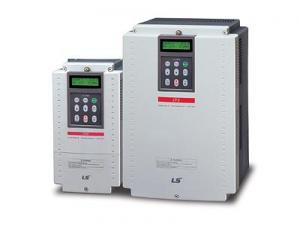
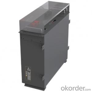
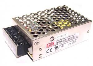
1. Application
AC/DC inverter is designed for switching DC24V to AC110-220V. They can be usedoutdoors or on home appliance as emergency power. Usually, cord with AC powersocket and the DC power cord with DC battery. When the load connects to the DCpower cord with DC power, if the commercial power falls, the inverter will convert thebatttery voltage to AC voltage and go on supplying. When the commercial power restall,the inverter will switch to charge the battery by itself. When the battery is fully charged,it will stop automatically.
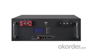
2. Feature
AC voltage available for AC 100V, 110V, 120V, 220V, 230V or 240V at request.Each unit contains two AC sockets available for two pin plugs.Automatic function change for inverter or batttery charge.Selective 4 AC voltage for each unit, such as when AC 110V, it will be available for AC110V, 120V, 130V and 140V.Different led indicator for function of inverter and charger.Each unit contain a AC cord for AC input voltage besides.Model ZUP-300 and ZUP-300A unit contains an extra power cord for DC battery.Products applicable for:
A. Personal computer.
B. Various video/audio equipment. (TV, casset, tape record, etc.)
C. Small motor equipment.
D. Various lighting equipment. Protection:
a. Protection for short circuit and polarity reverse of battery.
b. Overload fuse protection for charging current, input voltage and output voltage.
3. Specification
| Type | DC Voltage | Capacity | Charging Current |
| ZUP-300VA | DC12V, 24V | max.300W | max.25A |
| ZUP-500VA | DC12V, 24V | max.500W | max.35A |
| ZUP-1000VA | DC12V, 24V | max.1000W | max.35A |
| ZUP-1500VA | DC12V, 24V | max.1500W | max.45A |
| ZUP-2000VA | DC12V, 24V | max.2000W | max.60A |
| ZUP-3000VA | DC24V, 48V | max.3000W | max.90A |
| ZUP-5000VA | DC24V, 48V | max.5000W | max.150A |
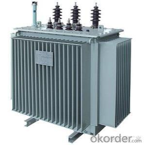
- Q:S11-1250kVA transformer oil capacity how much
- S11-1250kVA transformer oil capacity is 550kg, the pressure of the relevant information will be marked on the nameplate, the nameplate has the relevant parameters.
- Q:I want to know how much the current will increase. But the transformers i'm looking at VCT VT10000 - 10,000 Watts Heavy Duty Continuous Use 110V / 220V / 240V Step Up / Step Down Voltage Transformer or 15,000 Watt Step Up and Step Down Voltage TransformerI figure the whats is the total possible power and if you divide the power by the intial voltage you get the current and if you divide by the out put voltage you get the final current? but what if you input doesn't equal 15000 watts or whatever the power is?
- Bascally you are right. Watts is the maximum power, and dividing that by voltage provides amps. The transformer will pass what its load is consuming. If there is not enogh source eupply for the load, the source will burn out or blow its fuse/breaker.
- Q:I have a packaged heat pump w/ Emergency Heat that is not working and does not come on at all. No lights or anything even when I switch it to emergency heat. Someone said that it could be my low voltage transformer. What is that and how do I check it?
- You need to check the breaker fist and the disconnect on the unit. Then after verifying with a Volt meter that you have power. Your going to need to remove the panel on the unit. There should be a circuit board with a LED light blinking (this is assuming you have power), Count the number of flashes the look on the back of the panel or the installer manual. This will give you the fault code of what has failed. To test the low voltage transformer, again you need to verify that the unit has power. You will need to use a volt meter. The other possibility is you have a failed contactor or failed capacitor. To veriy your thermostat is working try turning on the blower (fan) to ON. If the fan comes on then you have power to the unit, and your low voltage transformer is working. Also, if your thermostat has batteries in it and if they are dead this will cause a no heat issue. Heat pumps are not easy to trouble shoot via the internet. I highly recommend you call a professional out to properly fix the unit. Remember IF you decided to go fishing and try and fix it, your dealing with HIGH voltage and sensitive electronics. So, poking around really is not a good idea.
- Q:describe a stabilised transformer
- A stablized Transformer is to step dwon or step up the voltage which is called stabilizer also.
- Q:How do transformers work detailed descriptions please. Also how are the voltages stepped up or down?
- A transformer is a device that can be used to increase voltage and decrease current (or vice versa). It uses AC power and is based on Faraday's law of induction (mutual induction). A transformer is made up of two coils, each with a different number of turns, linked magnetically through a soft iron core. The magnetic flux from one coil links the other through the core. When the flux in one coil changes, the flux passing through the other will change, inducing a voltage (emf) in the second coil. The coil connected to the AC power source is known as the primary coil (number of turns Np), while the coil in which voltage is induced is known as the secondary coil (number of turns Ns). If the primary coil sets up a changing flux, the voltage in the secondary coil depends on the number of turns in the secondary. The transformer is assumed to be ideal in which the resistance of the coils is negligible and all the flux in the core links both primary and secondary windings. There will be no energy loss in an ideal transformer.
- Q:I needto know the full conditions of parallel operation of transformers including details about vector groups.
- I am putting 1 QA for reference. Question If I parallel three 2MVA 22/11kV three phase 50Hz Dyn11 transformers of the same voltages, vector groups and impedances, do I connect all three star points to earth or only one star point to earth? If I want to put a resistance in the neutral connection to earth (NER), do I only connect one which is common to all three or a seperate NER for each? Answer Dear Dario, I will start with the imepdance: every transformer shall have its own because it is there to protect against internal faults as well. You may install only one impedance but that will depend on your protection devices and what they measure, i.e. where you put your CTs and VTs. These impedances must have a disconnect switch. For the first part, it is very general to me but i figure your load is large Medium Voltage motors (a mill), because 2MVA seems little for distribution and a Y secondary in MV is tricky. All neutrals shall be interconnected and connected individually to earth. This is for the case where the only link you have in mind is gone, the whole system will go float; so again, for the first part: all three star points shall be connected. If you're already protected against lightning, then you don't need limitation in surge voltage, i advise not to install a resistor and not connect N to E, i.e. go for an IT system which provides you with two benefits: fault currents are small and it take more than one fault to trip and cause discontinuity to the service,
- Q:I would like to get my grandchild all the transformer movie dvds but don't know the names of all of them. please help and thanks
- Transformers, Transformers: Revenge of The Fallen, and Transformers: Dark of the Moon(comes out September 30). Hope I helped.
- Q:I love the movie transformers and cant wait till part 2.Anyone know anything about it specifically???
- I cannot STAND that movie. The live action version sucks so much c0ck and balls. The original 80s Transformers Movie animated version had WAY more robots and WAY more action. Mike Bay's piece of cinematic fecal matter had only a small group of robots who look NOTHING like the Transformers from the cartoon series, and it was all about that idiot Shia LeBeouf running around whining and acting like beyotch. Correct me if I'm wrong, but I paid to see a Transformers movie and got ripped off. The movie wasted my time with those stupid human characters, and the robots really didn't do much of anything. The story sucked and who actually gives a crap for Shia's character romantic life? Ugghh! What a turd of a movie painted and glamed up to look better than it actually was. Which is why I don't undertsand why people like this movie so much? It is an insult to the true Transformers fans.
- Q:How can the locations and polarity of the windings be tested on the various legs of a core when it has 2 open(circuited) three pahse windings (III and iii)?what measurements are required , assuming that the transformer is so enclosed that only the 12 winding terminals are visible?Ohmmeter , voltmeters , a single phase voltage supply are available.
- It sounds like you have a three phase transformer. In the cover plate there normally is a drawing to guide you on what you want to do. Most trans formers can have input voltages of 440 volts in to 240 ouput. but some can provide 115 volts on the output if wired correctly. Any transfomer compnay website provide wiring drawings that pretty match everyones transformers. Contact the manufacturer of the transformer for instructions.
- Q:HiCan anybody help with the below question?A 400V, 3 phase supply is connected through a 3 phase loss-free transformer of ratio 1:1, which has its primary connected in mesh and secondary in star, to a load comprising three 20 ohm resistors connected in deltaCalculate the currents in the transformer windings, in the resistors and in the lines to the supply and the load. Find also the total power supplied and the power dissipated by each resistor.Thanks in advance
- The transformer is connected delta-wye (mesh-star), so the secondary voltage is: Vs400V x sqrt(3) 692.82V (line-to-line) Current in each resistor is: IrE/R692.82V/20ohm34.64A Line current on secondary is: Ils34.64A x sqrt(3) 60.00A Current in each secondary winding: Isw Ils 60.00A Current in each primary winding: Ipw Isw 60.00A (because windings are 1:1) Primary line current: Ilp Ipw x sqrt(3) 60.00A x sqrt(3) 103.92A Check: Primary and secondary kVA should be the same: kVAp400Vx103.92Axsqrt(3)/100072.0kVA kVAs692.82Vx60.00Axsqrt(3)/100072.0k It checks Since load is purely resistive, kVAkW. Total power: 72.0kW Power per resistor: 72.0kW/3 24kW
1. Manufacturer Overview |
|
|---|---|
| Location | |
| Year Established | |
| Annual Output Value | |
| Main Markets | |
| Company Certifications | |
2. Manufacturer Certificates |
|
|---|---|
| a) Certification Name | |
| Range | |
| Reference | |
| Validity Period | |
3. Manufacturer Capability |
|
|---|---|
| a)Trade Capacity | |
| Nearest Port | |
| Export Percentage | |
| No.of Employees in Trade Department | |
| Language Spoken: | |
| b)Factory Information | |
| Factory Size: | |
| No. of Production Lines | |
| Contract Manufacturing | |
| Product Price Range | |
Send your message to us
AC-DC Inverter DC24V to AC110-220V
- Ref Price:
-
- Loading Port:
- Shanghai
- Payment Terms:
- TT OR LC
- Min Order Qty:
- -
- Supply Capability:
- 10000pcs pc/month
OKorder Service Pledge
OKorder Financial Service
Similar products


New products
Hot products

Hot Searches
Related keywords

