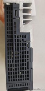


Three-Phase Or Single-Phase Universal Type MR-J4-20B Servo Amplifier
- Ref Price:
-

- Loading Port:
- Shanghai
- Payment Terms:
- TT OR LC
- Min Order Qty:
- 1 kg
- Supply Capability:
- 2000 kg/month
OKorder Service Pledge
OKorder Financial Service
You Might Also Like


Item specifice
Specification of sscnetiii / h mr-j4-20b for Mitsubishi servo amplifier 200W:
[output]
. rated voltage: three-phase ac170v
. rated current: 1.5A
[main circuit power input]
. power frequency: three-phase or single-phase ac200v ~ 240V 50Hz / 60Hz
. rated current: 1.5A
. allowable voltage variation: three-phase or single-phase ac170v ~ 264v
. allowable frequency variation: ± 5%
. capacity of power supply equipment: 0.5kva
. surge current: 30A (reduced to about 3A after 20ms)
[control circuit power input]
. power frequency: single phase ac200v ~ 240V 50Hz / 60Hz
. rated current: 0.2A
. allowable voltage variation: three-phase or single-phase ac170v ~ 264v
. allowable frequency variation: ± 5%
. power consumption: 30
. surge current: 20 ~ 30A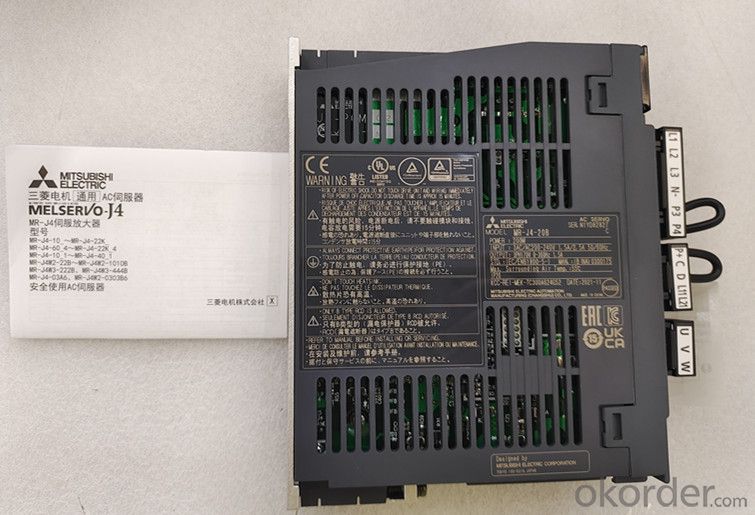
[power supply for interface]
. voltage? Frequency: DC24V ± 10%
. power capacity: 0.3A (including CN8 connector signal)
[control mode] sine wave PWM control current control mode
[dynamic brake] built in
[communication function]
. USB: connection with personal computer, etc. (corresponding to Mr
configurator2)
[position control mode]
. maximum input pulse frequency: 4mpps (differential input), 200kpps (open
collector input)
. positioning feedback pulse: encoder resolution (resolution of servo motor per
revolution) 22 bits
. command pulse magnification: electronic gear A / b times a = 1 ~ 16777216, B
= 1 ~ 16777216, 1 / 10 < A / b < 4000
. positioning completion pulse width setting: 0pulse ~ ± 65535pulse (command
pulse unit)
. excessive error: ± 3 Revolutions
. torque limit: set through parameter setting or external analog input (dc0v ~
+ 10V / maximum torque)
[speed control mode]
. speed control range: analog speed command 1:2000, internal speed command
1:5000
. analog speed command input: dc0v ~ ± 10V / rated speed (the speed at 10V can
be changed through [pr.pc12])
. speed change rate: ± 0.01% (load change: 0% ~ 100%), 0% (power change: ±
10%) ± 0.2% (ambient temperature: 25 ± 10 ℃). Only when analog speed command
is available
. torque limit: set through parameter setting or external analog input (dc0v ~
+ 10V / maximum torque)
[torque control mode]
. analog torque command input: dc0v ~ ± 8V / maximum torque (input impedance:
10K? ~ 12K?)
. speed limit: set through parameter setting or external analog input (dc0v ~
± 10V / rated speed)
[protection function]
Overcurrent protection, regenerative overvoltage protection, overload
protection (electronic thermal relay), servo motor overheating protection
Encoder abnormal protection, regeneration abnormal protection, insufficient
voltage protection, instantaneous power failure protection
Overspeed protection and excessive error protection
[safety function] sto (IEC / en 61800-5-2)
[safety performance]
. third party certification specification: EN ISO 13849-1 type 3 PL D, en 61508
SIL 2,
EN 62061 SIL CL2,EN 61800-5-2 SIL 2
. response performance: less than 8ms (STO input off → energy cut-off)
. test pulse input (STO): test pulse cycle: 1Hz ~ 25Hz test pulse off time:
max. 1ms
[structure (protection level)] self cooling open (IP20)
[compact installation] adjustable
[weight] 0.8kg
- Q:I know that someone made a transformer movie. But wouldn't DBZ the movie be a lot better!?!?!?
- If DBZ is Dragon Ball Z, the answer to your question is no. I say this not out of opinion but out of America's taste in entertainment. America as a whole doesn't tend to enjoy Japanese style entertainment. Transformers is a movie based on aliens and robots. DBZ is mostly based on magic and such. America likes stuff that they can grasp and make sense of.
- Q:I am working on a lengthy project and have one little area that I am not sure how to answer. I need to know how to size a transformer for a building. Does anybody know the equation or method for doing this? The service coming in is 480Y/277V and the step-down is to a 240/120 single phase panel. Any help is great! Thanks
- buildings come in all sizes. Some use a lot of power, perhaps because of lots of machinery. Others use a much smaller amount. So you need to calculate or estimate the amount of power the building will be using. If you know the square foot total and use of the building (industrial, office, etc) there are probably tables that will give you a guess. One 240/120 panel for the entire building? That implies a very small building, as must buildings distribute 3 phase 208 volts, and have numerous subpanels. .
- Q:Why can autotransformers be used as safety transformers? Isolation transformer is a variable ratio of 1 transformer, why has a security role?
- The high and low voltage side of the autotransformer is realized by tapping in a coil, and there is no magnetic connection between the two times and there is an electrical connection, so it can not be used as a safety transformer. Isolation transformer high and low voltage coil is separated, the only magnetic connection between the two there is no electrical contact, so the role of security protection.
- Q:I was wanting to buy my little brother a transformer toy, but not one of these cheap ones you buy today, but one you actual transform by yourself like when I was younger. So whats a good website where I can find some for him and me to play with, and I don't really want to spend to much on them, just enough.
- Amazon
- Q:hi , i got some electronics frm asia( like camera and hair dryer) , which can only be used in 220 volts. which converter or transformer sud i use which changes 110 volt to 220 volt ? and where can i get it ? i searched for it . but i found converters that change 220 v to 110 volt :(
- Check Hammond, they have auto transformers that can be wired either step down or step up. You need to know the total wattage of the devices you have , and choose the largest one. Frequency, hopefully, is not an issue here.
- Q:A transformer rises the voltage in proportion of 1 to 10. If the power in the primary coil is 100 watts, we should expect a power of ____ watts in the secondary coil. a) 10b) 100c) 1,000
- As that of primary:100.
- Q:I use a 1000 watt transformer for my tv, dvd player, cd player, game cube and nintendo (only 2 can be plugged in at a time or it is a fire hazard). The transformer is very strong and flips the circuit breaker if anything else in the house is plugged in and I try to plug that in. I'd rather not have to unplug everything to plug it in but I am worried I am wasting electricity if I keep it plugged in. So my question is does transformers use energy if they are plugged in and the appliances plugged into it aren't turned on? Also, do you think I can use a smaller transformer for those items listed above if it does use energy? The boxes that I buy them in don't say, they just say what watt they are.I've tried to look it up but I can't understand any of it so thank you in advance for helping me.
- Yes they use electricity
- Q:Transformer voltage range of 10.5 ± 2 * 2.5% kV and 10.5 ± 5% kV What is the difference
- 1, the voltage range is the same, are 10kV ± 5%; 2, the difference is that the accuracy of different voltage regulator, 10.5 ± 2 * 2.5% kV transformer sub-switch has five stalls, respectively, 10.5 +5% kV, 10.5 + 2.5% kV, 10.5kV, 10.5-2.5% , 10.5-5% kV; and 10.5 ± 5% kV transformer section switch has three stalls, respectively .5 +5% kV, 10.5kV, 10.5-5% kV; 3,10kV transformer sub-switch three more for the power failure regulator transformer, and sub-section switch five for overload regulator of the transformer, relatively speaking, the fifth gear than the third gear section switch Much more complex, so the price should be slightly higher for the load change is relatively large, the voltage quality requirements of the relatively high important occasions.
- Q:I am learning about transformers and one of the items to calculate is the impedance. I need to calculate regular 60 Hz Core and Coil Shell Type Transformers Al wire in secundary, Cu Wire primary and use Epoxy paper for insulation.
- It's pretty difficult to calculate the impedances (there's more than one) entirely from the transformer's design data. It's easier and more usual to decide on an equivalent circuit (there are plenty available depending on how well you want to model the transformer) and then to determine the parameters by a mix of calculation and measurement. A pretty basic equivalent circuit which refers all impedances to the primary side, has the primary terminals connected first by Xm and Rc in parallel (the magnetising reactance and core loss resistance) and then by a third parallel branch containg a series connection of leakage reactance Xl, winding resistance Rw and an ideal transformer of turns ratio Np/Ns. Xm is best obtained from an open circuit test but could be calculated as the inductance of the primary winding. For the latter you'd need to know core dimensions, number of winding turns and the magnetising characteristic of the core iron. If you have conductor sizes and conductivities you can calculate the winding resistance Rw, referring the secondary part to the primary by multiplying it by (Np/Ns)?. You can deduce Rc from the losses measured on open circuit at nominal voltage and Rw from dc resistance measurements on the windings. If you know the specific hysteresis and eddy current losses of the core material, you can also have a good stab at calculating Rc. The leakage reactance is quite difficult to calculate from first principles - even designers usually resort to some empirical factors. Basically it's determined from the short circiut test which is at nominal secondary current. The ratio of primary volts to secondary surrent (referred of course) on secondary short circuit will get you close to Xl - you can adjust for Rw which can be determined from the losses on short circuit (core losses are absent here!) or by the two methods indicated above. It's normally Xl that's referred to as the transformer reactance and together with Rc and Rw, the impedance.
- Q:I have two-way transformer (120Vlt;240V) that has a surge capacity of 2000W and a continuous capacity of 1600W. The transformer is plugged into my wall socket and is, on its output side, attached to a power surge protector that leads to six separate sockets. There are periods where not all six sockets are in use - in this specific case, the only appliance is a 50W fan - and my question is, does the transformer still eat 1600W off my meter and waste most of it as heat, or is it nice and intakes maybe only 60W and inefficiently converts it to the required 50W? If the company/model comes into question, I can only say the transformer is of Taiwan origin - the company logo is a 'Z' with small D intersecting the two parallel lines of the former letter, all against a blue background - and has a model number of TC-2000. Many thanks.
- The power TRANSFORMED by a transformer is governed by the load connected to the transformer. So if you apply a 50W load, then the output of the transformer will be about 50W. No electrical component is perfect - all incur some kind of losses. In the case of transformers, there are two kinds of losses. Through losses (aka 'copper losses') are losses that occur as (and because) power is passing through the transformer and occur as a consequence of heating in the conductors that make up the windings of the transformer. The magnitude of copper losses depends on the design of the transformer, but on a small transformer might be something in the range of 1-5% of the power being transformed. So for your 50W, load, the copper losses might be as much as 2.5W. The other form of loss with a transformer is excitation loss. These are losses associated with magnetization of the iron core of the transformer. These losses are fixed and irrespective of the amount of power being transformed. On a small transformer, core losses could be as much as 1% of the transformer RATING. In your case, the rating is 1600w (that 2000W 'surge' rating is simply a short-time thermal overload capability - its not really a rating). So 1% of 1600 watts is 16 watts. So what that means is if the output of the transformer delivered to the load is 50 W, then the input to the transformer including losses might be 68.5W.
1. Manufacturer Overview |
|
|---|---|
| Location | |
| Year Established | |
| Annual Output Value | |
| Main Markets | |
| Company Certifications | |
2. Manufacturer Certificates |
|
|---|---|
| a) Certification Name | |
| Range | |
| Reference | |
| Validity Period | |
3. Manufacturer Capability |
|
|---|---|
| a)Trade Capacity | |
| Nearest Port | |
| Export Percentage | |
| No.of Employees in Trade Department | |
| Language Spoken: | |
| b)Factory Information | |
| Factory Size: | |
| No. of Production Lines | |
| Contract Manufacturing | |
| Product Price Range | |
Send your message to us
Three-Phase Or Single-Phase Universal Type MR-J4-20B Servo Amplifier
- Ref Price:
-
- Loading Port:
- Shanghai
- Payment Terms:
- TT OR LC
- Min Order Qty:
- 1 kg
- Supply Capability:
- 2000 kg/month
OKorder Service Pledge
OKorder Financial Service
Similar products


New products
Hot products