
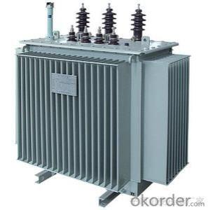
ZGS-200-1000-10 Combined transformer
- Ref Price:
-

- Loading Port:
- Shanghai
- Payment Terms:
- TT OR LC
- Min Order Qty:
- -
- Supply Capability:
- 1000sets set/month
OKorder Service Pledge
OKorder Financial Service
You Might Also Like


Production introduction
1.ZGS 11 combined transformer is one of the hightech products developed by our company on the basis of pad-mounted transformer.
2.Range of capacity:200-1000KVA.The product is suitable for the neutral-point insulation system or small-resistance grounding system in a 10KV distribution network,or neurtal-point solid grounding system of a three-phase four-wire system in a 400V distribution network.
3.Excellent design,reliable distribution,compact structure,light in weight,and low noise,ect;it has two types of cable outlets;ring net type and terminal type.
4.The product can be placed directly into the load center of 10KV network,thus the line loss is reduced and power distribution reliability is increased.
Performance characteristics
1.The ZGS11 combined transformer consists of high-voltage and low-voltage chambers and transformer tank in the operation chambers.
2.H.V.incoming lines in 10KV cross-linked cables are connected to load switch through knuckle connectors,straight plugs and sleeve sockets.
3.On the high-voltage side,a protection of double fuses(backup current-limiting fuse and plug-in type of fuse are used).
4.There are terminal type and ring net type high-voltage load switches for selection.
They are easy to connect,convert and reliable for power supply.
5.In the low-voltage chamber,a fixed type or drawable type is optional for the low-voltage switch cabinet according to user's requirement.Various low-voltage apparatus,such as metering and protection instruments are available.(Note:In general they are customized)
6.The oil tank is fully-sealed by corrugated radiators,which features compact and superior appearance.
Model designation
Applicable standards
GB1094.1-2-1996 Power Transformer
GB1094.3-5-2003 Power Transformer
JB/T10318-2002 Technical parameters and requirements for oil-immersed,non-crystal alloy iron core,distribution transformer.
Normal service conditions
Installation type:indoor/outdoor type
Ambient temperature:-25oC~+40oC
Altitude:≤1000m
Humidity:daily average value≤95%,monthly average value≤90%
Installation site:in places without corrosive gases,obvious dusts and water-vapour;the gradient is no more than 3% and no fierce shock.
Performance Characteristics
1.Compare with type "9" transformer,the product's no-load loss is reduced by 30% and thus the average annual operating costs can by reduced by 20.03%.
2.The transformer body,high voltage load switch fuses and no-excitation tapping switches are all put into the fully-sealed oil tank,which make good use of the space.Therefore,the overall size of the product is only 1/3 of that of the similar product.
3.The plug-in and out cable connection is easy for operation.
4.An obstacle protection is of two-stage fuses structure(backup current-limiting fuse and plug-in type fuse) which ensures a safe and flexible operation and more convenient for replacing of fuse.
5.The oil tank is fully-sealed,in which the oil is totally isolated from the outside.No leakage and maintenance free.
6.Excellent short-circuit proof capacity and high reliability.
Notes for placing orders
Transformer type:rated capacity kVA
Number of phases:three-phase single-phase
High voltage:kv/Low voltage:kv
Frequency:50HZ 60HZ
Tapping range:±2×2.5%±5%other
Connection group:Yyn0 Dyn11 other
Impedance voltage:4% 6% other
- Q:A transformer has a 100-turn primary coil and 1000-turn secondary coil. The primary is connected to a 120-V AC source and the secondary os connected to an electrical devic with a resistance of 1000 ohms.what will the voltage output of the secondary be?what current flows in the secondary circuit?what is the power in the seconday coil?what is the power in the primary coil ?what is the current drawn by the primary coil?
- The ratio of voltages in the windings of a transformer is the same as the ratio of turns of wire in the windings, so in this case the voltage ratio is 1 to 10. If you connect the primary to a source of 120 volts, the voltage induced in the secondary winding is 10 times as much, or 1200. If a (pure) resistance of 1000 ohms is connected to the secondary winding, the current (I) that flows is found by Ohm's Law: I E/R. Since E is 1200 volts and R is 1000 ohms, I 1200 / 1000, or 1.2 amperes. The power P in the secondary coil is found by multiplying the voltage by the current, so P 1200 times 1.2, or 1440 watts. Transformers are very efficient, and the power in the primary coil is essentially the same as that in the secondary, or 1440 watts. The current drawn by the primary coil is found by dividing the power by the voltage: 1440 divided by 120 12 amperes. Hope this answers all parts of your question.
- Q:Can the transformer be replaced with a component?
- If you say the transformer is a small power frequency transformer, then you can use switching power supply instead. If the substation with high-power transformers, there is no thing to replace.
- Q:After the calculation, due to the different cooling, the current density is different, I finished a winding section 96.5mm ?, secondary winding section 1562.5mm ? What are the specifications of the copper row? Another request for a transformer copper specifications table.
- Answer: no love language, all the text is boring.
- Q:even though the output voltage of a transformer can be much larger than the input voltage, the power output is nearly the same as the power input.Determine the relationship between the input and output current and the number of turns in the input and output coils.help!!!!!!!!thank you
- If turns ratio is N, output turns divided by intput turns, then voltage ratio is also N, and current ratio is 1/N For example, a 120 VAC transformer with a 12 volt 10 amp secondary will have a turns ratio of 1/10, a voltage ration of 1/10 (12/120) and a current ratio of 10 (1 amp in primary, 10 amps in secondary) .
- Q:A I have a 230V/12V, 3A step-down transformer. What will happen at primary side of transformer if I attach a 12V/5A device at secondary side? Will primary side attributes (such as voltage or current) change?
- I really am not sure what will happen on the primary side. But I can tell you that whatever you are powering on the secondary side won't get enough power to work properly for very long.
- Q:Can dry transformers and distribution cabinets be placed in the same room?
- Yes. Dry-type transformers are usually placed in the room with a shell, low-voltage cabinet is with the dry-type transformers together. The general practice is to flush the cabinet. And then connect the transformer with the low voltage cabinet directly in the cabinet to go. Outside can not see the connection of copper.
- Q:I got stuck in a problem while solving the previous exam question for my courseTwo transformers with unequal turn ratio and unequal ratings are connected in parallel and have the same secondary voltage. How will the load be distributed between them? Hence find the circulating current.I know how to find the circulating current when the secondary voltages are different. But how can there be a circulating current if the secondary voltage is same?And I know about the load distribution being inversely proportional to the line impedance of the transformers, but what will be the change taking circulating current into account?
- That you may put both the transformers on the same line on their essential aspects however they must have different hundreds at their out places. You ought to use a small load on a 200kva and better load on 500kva. For higher guidance are attempting reffering an electrical engineer near you. I am also an electrical engineer.
- Q:hi guys can any of you give me advice on wot i need 2do on removing and replacing a faulty line output transformer on a rear veiw projection tv as i have the part and the local tv shop wont fix it 4 me.wot would be the best way to discharge the power from it first and could i jus cut the 2 wires on the old 1 and use connector blocks to connect the new 1 in would this be ok to do or do it need to soilder connected on?. and is there any adjustments that would need to be done to the set when i have it installed be4 i turn it on any help much appreicated
- Solder the joints!!!!It is OK to use the old connectors!!!! Be sure that the power of the new transformer it is the same with the power of the old one.
- Q:1.Transformers are normally used to step up or step down alternating voltage or current. May dc also be used to step up or step down voltage or current? Motivate your answer?2.The supply voltage of a step down transformer is 240 volts and the winding ratio is 4,8 : 1. If there are 2000 turns on the primary winding calculate:2.1) The number of turns on the secondary2.2) The primary current when the secondary current is 15 A3. Calculate the secondary voltage of a transformer with supply voltage of 415 volts, the winding ration is 36 : 14.Can an Autotransformer be used to step up pulsating dc current? Motivate your answer.
- 1.strictly NO.DC cannot be used at all to step up and step down using transformer if you read the working of transformer,it works on the principle of electromagnetic induction. i.e. it depends on change of flux with time. it can only happen in ac voltages not in dc ones because in dc the volatge is fixed but in ac it changes with time and flux and current are directly proportional. 2. 2.1)it is step down transformer. so number of turns in primaryno. of turns in secondary NpNs 4.8/12000/Ns Ns2000/4.8 Ns416.6777 but no of turns needs to be an integer so Ns417 (round off) 2.2)Ip/IsNs/Np IpIs*Ns/Np 15*2000/417 71.94A 3) 415/Vs36/1 Vs11.53V 4) Yes. such transfomers are called pulse transformers.
- Q:High power transformers are very common, for obvious reasons. Much unlike homemade transformers that I've ever built, only out of tiny enameled #26 wire, that wouldn't power anything practical.I've tried using wire as large as #6 wire to wrap a homemade transformer, as what would be needed to connect externally to 10 kVA transformers, but that simply isn't practical. The wire is simply too stiff to wrap it in tight windings.Consider the example of a 225 kVA three phase transformer, that carries about 300 Amps of current on each of its secondaries that are 277 Volts. Externally, I'd need to connect with 400 kcmil wire, that is almost an inch in total diameter. What exactly do they do in order to build transformers at this high power?Do they parallel a whole bunch of tiny windings?Do they use a cooling fluid, so that tiny wire can have a much greater ampacity?Or do they also use big wire, but the way it is constructed somehow relieves the strain resulting from wrapping it? Heat treating the metal, perhaps.
- The transformers are wound using machinery that can bend the heavy wire as required. Parallel wires are used, but they are not usually tiny, but smaller that what would be needed for single wires. Transformers are wound with flat strap-like conductors rather than round wires. Liquid cooling allows the maximum current in a given size wire. PS Not everything described is used for every large transformer. Construction techniques vary. There may be other techniques and designs used also.
1. Manufacturer Overview |
|
|---|---|
| Location | |
| Year Established | |
| Annual Output Value | |
| Main Markets | |
| Company Certifications | |
2. Manufacturer Certificates |
|
|---|---|
| a) Certification Name | |
| Range | |
| Reference | |
| Validity Period | |
3. Manufacturer Capability |
|
|---|---|
| a)Trade Capacity | |
| Nearest Port | |
| Export Percentage | |
| No.of Employees in Trade Department | |
| Language Spoken: | |
| b)Factory Information | |
| Factory Size: | |
| No. of Production Lines | |
| Contract Manufacturing | |
| Product Price Range | |
Send your message to us
ZGS-200-1000-10 Combined transformer
- Ref Price:
-
- Loading Port:
- Shanghai
- Payment Terms:
- TT OR LC
- Min Order Qty:
- -
- Supply Capability:
- 1000sets set/month
OKorder Service Pledge
OKorder Financial Service
Similar products


New products


Hot products


Related keywords

