

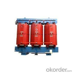
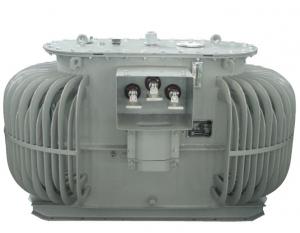
Oil-immersed power transformer of 35kV
- Ref Price:
-

- Loading Port:
- China Main Port
- Payment Terms:
- TT OR LC
- Min Order Qty:
- -
- Supply Capability:
- -
OKorder Service Pledge
OKorder Financial Service
You Might Also Like


Oil-immersed power transformer of 35kV
1. Product
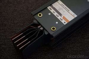
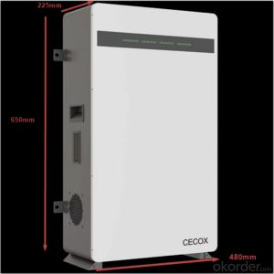
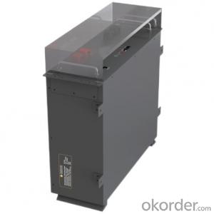
S9 series power transformer of 35kV is mainly used for the transmission and distribution in the power system of voltage level 35kV and rated frequency 50-60Hz, the capacity of it is 50-31500kVA. The iron core adopts silicon steel sheet with high permeability, full-oblique joints, no punching, and colligated and taken up with semi-dry epoxy fiberglass banding. The fuel tank has three types of radiators: flat tube type, corrugated type and chip type. The 800kVA above transformers are equipped with gas relay, pressure relief valve, oil tank with diaphragm and remote thermometer components.
The transformers of 3150kVA and above are equipped with oil refiner. The characteristics of products are low loss, low noise, save power and so on.
SZ9 series on-load-tap-changing power transformer of 35kV is equipped with tap changer, the voltage regulating range of it is ± 3 × 2.5%. The voltage adjustment can be controlled by manual or automatic through control box. The structures,performances and characteristics of the transformer are as the same as the power transformer of S9 series for 35kV.
The products conform with the GB/T6451-2008 standards.
2. Technical parameter
35kV S9 series distribution transformer technical parameter
Model | Rated Capacity (kVA) | Rated voltage (kV) | Loss (W) | Impedance of short-circuit(%) | No-load current(%) | Label number of connecting group | Weight (kg) | Outside DimensionL x W x H(mm) | Gauge (mm) | ||||
HV | LV | No-load | load | Body | Oil | Ttotal weight | |||||||
S9-50/35 | 50 | 38.5±5% 35±5% | 0.4 | 0.21 | 1.27/1.21 | 6.5 | 2.0 | Yyn0 Dyn11 | 345 | 260 | 820 | 1140×955×1760 | 550/550 |
S9-100/35 | 100 | 0.29 | 2.12/2.02 | 1.8 | 408 | 390 | 1070 | 1180×1070×1910 | 550/550 | ||||
S9-125/35 | 125 | 0.34 | 2.50/2.38 | 1.7 | 415 | 470 | 1100 | 1180×1090×2000 | 550/550 | ||||
S9-160/35 | 160 | 0.35 | 2.97/2.83 | 1.6 | 423 | 555 | 1295 | 1180×1100×2035 | 550/550 | ||||
S9-200/35 | 200 | 0.43 | 3.50/3.33 | 1.5 | 524 | 655 | 1540 | 1260×1150×2075 | 550/550 | ||||
S9-250/35 | 250 | 0.51 | 4.16/3.95 | 1.4 | 550 | 825 | 1755 | 1330×1200×2155 | 660/660 | ||||
S9-315/35 | 315 | 0.61 | 5.01/4.77 | 1.4 | 640 | 945 | 2010 | 1390×1250×2220 | 660/660 | ||||
S9-400/35 | 400 | 0.73 | 6.05/5.76 | 1.3 | 740 | 1125 | 2390 | 1720×1260×2285 | 660/660 | ||||
S9-500/35 | 500 | 0.86 | 7.28/6.93 | 1.2 | 805 | 1289 | 2710 | 2045×1290×2415 | 660/660 | ||||
S9-630/35 | 630 | 1.04 | 8.28 | 1.1 | 885 | 1455 | 3040 | 2155×1320×2250 | 820/820 | ||||
S9-800/35 | 800 | 1.23 | 9.90 | 1.0 | 1050 | 1800 | 3700 | 2265×1340×2700 | 820/820 | ||||
S9-1000/35 | 1000 | 1.44 | 12.15 | 1.0 | 1335 | 2115 | 4510 | 2495×1380×2885 | 820/820 | ||||
S9-1250/35 | 1250 | 1.75 | 14.67 | 0.9 | 1445 | 2610 | 5045 | 2595×1410×2910 | 1070/1070 | ||||
S9-1600/35 | 1600 | 2.12 | 17.55 | 0.8 | 1490 | 2840 | 5740 | 2680×1590×2970 | 1070/1070 | ||||
Note: Load values before “/” are for Dyn11 connection and values after “/” are for Yyn0 connection.
35kV no excitation voltage regulating power transformer technical parameter
Type specification | Rated Capacity kVA | Rated voltage(kV) | Loss (W) | Impedance of short-circuit (%) | No-load current(%) | Label number of connecting group | Weight(kg) | Outside DimensionL x W x H (mm) | Gauge(mm) | ||||
HV | LV | No-load | load | Body | Oil | Total weight | |||||||
S9-800/35 | 800 | 38.5±5% 35±5% | 3.5 6.3 10.5 | 1.23 | 9.9 | 6.5 | 1.0 | Yd11 Ynd11 | 1150 | 1800 | 3900 | 2265×1340×2700 | 820/820 |
S9-1000/35 | 1000 | 1.44 | 12.15 | 0.9 | 1335 | 2115 | 4510 | 2495×1380×2885 | 820/820 | ||||
S9-1250/35 | 1250 | 1.76 | 14.67 | 0.8 | 1445 | 2610 | 5045 | 2595×1410×2910 | 1070/1070 | ||||
S9-1600/35 | 1600 | 2.12 | 17.55 | 0.7 | 1490 | 2840 | 5740 | 2680×1590×2970 | 1070/1070 | ||||
S9-2000/35 | 2000 | 2.72 | 19.35 | 0.6 | 1574 | 3280 | 6410 | 2690×1620×3100 | 1070/1070 | ||||
S9-2500/35 | 2500 | 3.20 | 20.70 | 0.56 | 1885 | 3860 | 7695 | 2730×1900×3000 | 1070/1070 | ||||
S9-3150/35 | 3150 | 3.80 | 24.30 | 0.56 | 2145 | 4610 | 8980 | 2660×2900×3100 | 1070/1070 | ||||
S9-4000/35 | 4000 | 4.52 | 28.80 | 0.48 | 2270 | 5330 | 10060 | 2800×2865×3365 |
| ||||
S9-5000/35 | 5000 | 5.40 | 33.03 | 0.48 | 2580 | 6330 | 11670 | 3460×2940×3430 | |||||
S9-6300/35 | 6300 | 6.56 | 36.90 | 0.42 | 2840 | 7440 | 13430 | 3800×2770×3355 | |||||
S9-8000/35 | 8000 | 9.00 | 40.50 | 0.42 | 3500 | 9650 | 17200 | 4400×3000×3520 | |||||
S9-10000/35 | 10000 | 10.88 | 47.70 | 0.40 | 4400 | 12200 | 21000 | 3800×3550×3750 | |||||
S9-12500/35 | 12500 | 12.60 | 56.70 | 0.40 | 5000 | 13740 | 24500 | 4500×5650×3900 | |||||
S9-16000/35 | 16000 | 15.20 | 69.30 | 0.40 | 5520 | 16800 | 27800 | 4800×3700×4050 | |||||
S9-20000/35 | 20000 | 18.00 | 83.70 | 0.32 | 5900 | 19020 | 31100 | 5240×3830×4040 | |||||
S9-25000/35 | 25000 | 21.38 | 99.00 | 0.32 | 7200 | 23400 | 37600 | 5520×3800×4460 | |||||
S9-31500/35 | 31500 | 25.28 | 118.80 | 1.0 | 7660 | 26080 | 42200 | 5660×3800×4590 | |||||
35kV 2000~12500kVA load voltage regulating power transformer technical parameter
type Specification | Rated Capacity(kVA) | Rated voltage (kV) | Loss (kW) | Impedance of short-circuit(%) | Label number of connecting group | Weight(kg) | No-load current (A) | |||
No-load | Load | Body | Oil | Total weight | ||||||
SZ9-2000/35 | 2000 | 35 | 2.88 | 20.25 | 6.5 | Yd11 | 2.9 | 20.25 | 0.9 | 0.80 |
SZ9-2500/35 | 2500 | 3.40 | 21.73 | 3.44 | 21.74 | 0.9 | 0.80 | |||
SZ9-3150/35 | 3150 | 38.5 35 | 4.04 | 26.01 | 7.0 | 4.09 | 26.0 | 0.81 | 0.72 | |
SZ9-4000/35 | 4000 | 4.84 | 30.69 | 4.95 | 30.7 | 0.81 | 0.72 | |||
SZ9-5000/35 | 5000 | 5.80 | 36.00 | 5.85 | 36.0 | 0.77 | 0.68 | |||
SZ9-6300/35 | 6300 | 7.04 | 38.70 | YNd11 | 7.02 | 38.7 | 0.77 | 0.68 | ||
SZ9-8000/35 | 8000 | 9.84 | 42.75 | 7.5 | 10.0 | 42.7 | 0.68 | 0.60 | ||
SZ9-10000/35 | 10000 | 11.60 | 50.58 | 11.7 | 50.6 | 0.68 | 0.56 | |||
SZ9-12500/35 | 12500 | 13.68 | 59.85 | 8.0 | 13.77 | 59.85 | 0.63 | 0.54 | ||
- Q:1000KVA transformer no-load loss is how much?
- No-load loss is 1% of the rated capacity of the transformer, then 10KVA per hour. A year down about the loss is 87600KVA.
- Q:Hi, I need a High Frequency( example~200khz) High voltage(200 000v) power supply at low microcurrent, I know that a Tesla coil fits the bill very easily . But I need to manually VARY the frequency(say from 100khz to 200khz ) while keeping the High voltage the same? Is this possible, Can some one guide me where I can buy or build this? Can I just for instance connect just a van de graaf or a rectified Tesla Coil to a function generator? If not what do I need to do to achieve what I want? I have been searching without help so your support is much appreciatedThanks
- The Tesla coil needs to operate at the same resonant frequency on both the primary and secondary sides of the loosely coupled transformer. The resonant frequency is set by the inductance and capacitance of each side. The problem is there are no high voltage solid state capacitors (varactor diodes like you see in r.f. receivers that adjust the tank circuit frequency) on the primary side, and no way to adjust the top hat toroid capacitor on the secondary side (unless maybe it was a mylar covered balloon with vacuum deposited aluminum that could be remotely inflated or deflated). So you are stuck with whatever high voltage capacitor and toroid top hat you have on hand, and the inductance of the coils you wind that ends up being the resonant frequency. Even then it takes a lot of fiddling to get both in tune to give the maximum voltage output. The input frequency to the primary coil (the 555 circuit used in the step up with the flyback transformer- its frequency was chosen solely due to the flyback's frequency design) has little to do with the primary's resonant frequency; again that is set by the capacitor used and the size and number of turns of the primary coil.
- Q:The difference between the reflection impedance of the ideal transformer and the hollow core transformer is different.
- The ideal transformer reflection impedance is the equivalent impedance of the load resistance equivalent to both ends of the primary coil, directly across the primary coil at both ends, in parallel with the primary circuit, and the nature of the reflection impedance and load impedance of the same nature.
- Q:i have one transformer, but i don't know what wattage does he haveso can someone help me with that
- If the transformer has both the voltage and the current or amps listed on it just multiply the two to get wattage. A 110 volt transformer at 5 amps will be 550 watts. If the transformer doesn't list both of these specs, try looking up the brand and part number to see if you can find them. That would be the only way. A bigger transformer will generally have a higher wattage rating but you won't know exactly what the rating is.
- Q:Hi i'm considering starting to read comics. transformers comics to be exact. i live in ipswich so i walked into my local store (central city comics) there was alot to choose from and i know that there is loads of transformers comics out there I need some advice on starting a collection
- I can't give direct advice because it's all a matter of preference, but I can clear up some confussion for you Genertation 1 issues are hard to get a hold of singley and collect, so buy the collections if you're interested in seeing how it all began and (Generation 2 follows but hasn't been collected yet) Books with the Dreamwave brand are bogus and cancelled (because of the company president's brilliant bookkeeping skills). It's a different take on G1 but it wasn't very good or very long The War Within is the official history of Optimus Prime, Megatron and Cybertron in the early stages of the war. Dreamwave released them, but IDW collected them in a handy Omnibus (Dreamwave also left the third mini series incomplete) Armada/Energon are a comic book continiuty of the animated series. Dreamwave's closure left the series incomplete, so don't bother investing too much stock into these unless you think they're worth a look IDW published many different series, books with the IDW brand are a brand new reboot of G1, and they also published other series such as Beast Wars (continuation of animated series), Hearts of Steel (Steam age Transformers), Generations (reprints of selected G1 issues), and Movie universe books (events between movies) Here's the order of IDW's new comic series: Megatron Origin Infiltration Stormbringer Escalation New Avengers/Transformers Devastation Maximum Dinobots All Hail Megatron Ongoing series (currently up to #22) Heart of Darkness + a bunch of Spotlights about different characters and mini series (Ironhide, Bumblebee, Drift, Last Stand of the Wreckers) The movie universe books are in order: Revenge of the Fallen Defiance/Dark of the Moon Foundation Transformers Saga of the All Spark/ Official Prequel Transformers Transformers Reign of Starscream Revenge of the Fallen Alliance Revenge of the Fallen Revenge of the Fallen Nefarious Revenge of the Fallen: Tales of the Fallen Dark of the Moon Rising Storm Dark of the Moon
- Q:Transformer three-phase imbalance which harm
- 1, when the line is not full-phase operation, the zero sequence current is equivalent to the load current, then the line with its adjacent line zero sequence current may be large, even greater than the zero sequence backup protection settings, if not quickly cut Non-full-phase operation of the line, it may lead to adjacent line malfunction, leap-off; 2, for 220kV and above generator transformer group and machine-side circuit breaker, due to non-full phase operation during a larger negative sequence current, the generator, the transformer may cause a greater damage to the equipment.
- Q:I'm an intern at an aluminium smelter and am part of the power plant there. They replaced the 33 kV transformers with the 132 kV ones because of an increase in the demand from the smelter. But what are the advantages of such a replacement, besides the obvious decrease in heat loss?
- I think you have terminology problems. 132 kV versus 33 kV is a voltage 4 time higher. So an application that used 33 kV would be severely overloaded at 132 kV. I suspect you mean 132 kVA vs 33 kVA? That is totally different. And represents the power level of the transformer by a factor of 4. Why do you think there would be less heat loss? .
- Q:I heard that a transformer is like a ratio device for amps and volts, but I know there must be more to it. How exactly does it work, and what happens when it doesn't have enough current, but enough voltage?
- A transformer is a pretty simple device, it consist of two or more windings around a iron or ferret core. First keep in mind only AC works in a transformer. Transformers work by the primary winding generating a magnetic flux in the core. The second winding will pick up this flux and convert it back to voltage. Note: Michael Faraday in 1831 discovered this interaction which made transformer, motors and generators possible. Basic rule: Power in Power out - some losses. The ratio of the turns on the primary to the secondary will determine the increase. ie 10 turn on a primary and 100 turn on a secondary will step the voltage up x 10. The turns ratio control the step up or step down of the transformer. More winding on the secondary than the primary will cause a step up of voltage, Less winding will step down. The current carrying capacity of the transformer is controlled by the size of the wire. If you exceed the current carrying capacity you will burn out the winding. Heaver wire can handle more current. I know you have been interested in High Voltage step up transformers. The most voltage a transformer can produce is about 12KV. Usually after that it become extremely difficult to isolate the wires in the secondary to keep the current from jumping from one winding to another and burning out the transformer. The way to step up the voltage after the transformer is to use a voltage multiplier cascade.
- Q:A stepdown transformer is used for recharging the batteries of portable devices such as tape players. the turns ratio inside the transformer is 13:1 and it is used with 120 V rms household service. if a particular ideal transformer draws 0.350 A from the house outlet, what are the voltage and the current supplied to a tape player from the transformer. How much power is delivered?
- I'm not going to do your homework for you, but here is how to set up the problem. Given: Input Voltage 120 V Input Current 0.350 A Turns Ratio 13:1 For an ideal transformer, VA(in) VA(out) Transformer turns ratio can be computed as V(in) ÷ V(out). Use algebra to solve for Output voltage. Output Voltage Input Voltage ÷ Turns Ratio The turns ratio can also be computed as I(out) ÷ I(in). Again, use algebra to solve for the outut current I(out) Output Current Input Current x Turns Ratio This is an AC power problem, so we have to either assume unity power factor, or label our power calculations as apparent power (VA). Apparent Power Voltage x Current As an ideal transformer, you can calculate the power on either the input or output side of the transformer. If you get different numbers, you did something wrong. Power V(in) x I(in) Power V(out) x I(out)
- Q:How we can check the output wattage of any voltage transformer? For example if we buy a voltage stabliser for television or A/C, how we can be certain that the output watts provided by the stabiliser will suit our appliance? Is there any device to check the output watts, if yes, then how to?Please help.
- Watts is the volts x amps. You will know the supply voltage and you can use an amp meter to find out the amps. For example 230V x 3A is 690 Watts.
1. Manufacturer Overview |
|
|---|---|
| Location | |
| Year Established | |
| Annual Output Value | |
| Main Markets | |
| Company Certifications | |
2. Manufacturer Certificates |
|
|---|---|
| a) Certification Name | |
| Range | |
| Reference | |
| Validity Period | |
3. Manufacturer Capability |
|
|---|---|
| a)Trade Capacity | |
| Nearest Port | |
| Export Percentage | |
| No.of Employees in Trade Department | |
| Language Spoken: | |
| b)Factory Information | |
| Factory Size: | |
| No. of Production Lines | |
| Contract Manufacturing | |
| Product Price Range | |
Send your message to us
Oil-immersed power transformer of 35kV
- Ref Price:
-
- Loading Port:
- China Main Port
- Payment Terms:
- TT OR LC
- Min Order Qty:
- -
- Supply Capability:
- -
OKorder Service Pledge
OKorder Financial Service
Similar products


New products
Hot products


Related keywords

