
Supplier 1050 O Aluminum Sheet For Roof Sheets
- Ref Price:
-

- Loading Port:
- Tianjin
- Payment Terms:
- TT OR LC
- Min Order Qty:
- 500 g/m²
- Supply Capability:
- 200000 g/m²/month
OKorder Service Pledge
OKorder Financial Service
You Might Also Like
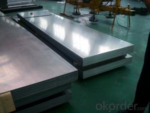
Supplier 1050 O Aluminum Sheet For Roof Sheets


Main Specification | |
Alloy | AA1*** (AA1050, 1060, 1070, 1085, 1100 and etc.) |
AA2*** (AA2014, 2017, 2019, 2024 and etc.) | |
AA3*** (AA3003, 3004, 3005, 3104 and etc.) | |
AA5*** (AA5005, 5052, 5082, 5083, 5182 and etc.) | |
AA6*** (AA6061, 6082 and etc.) | |
AA7*** (AA7050, 7075, 7475 and etc.) | |
AA8*** (AA8011) | |
Temper | O; H112, H14, H16, H18, H22; T3, T4, T6, T351, T451, T651 and etc. |
Thickness | 0.15-450mm |
Width | 300-3000mm |
Length | 500- 12000mm |
Standard | GB/T 3198-2006 |
FAQ
Q: Can you provide free samples?
A: Yes, free samples will be sent to you on freight at destination.
Q: Can I get your latest catalogue?
A: Yes, it will b.e sent to you in no time.
Q: What is the MOQ?
A: 5 tons
Q: What are your payment terms?
A: We accept L/C, D/A, D/P, T/T, West Union,etc
- Q:What do engineers need to learn from mechanical design as an electronic hardware engineer?
- Precision machinery design and traditional mechanical design, the general principle is the same, but its size should be as small as possible, the manufacturing precision is much higher, so the original mechanical design knowledge to meet the requirements of precision machinery design.
- Q:The strength criterion of mechanical parts design is briefly introduced
- 1, the strength criterion requires that the working stress of the mechanical parts should not exceed allowable stress [Sigma]. The formula is typical: (3-16) lim - ultimate stress of brittle materials by static stress on the ultimate strength, the static stress of plastic materials, the yield limit of zero stress the fatigue limit. S - Safety factor. 2. stiffness criteria mechanical components are subject to elastic deformation when subjected to load. Stiffness is the ability to resist deformation of materials, mechanical parts, or structures subjected to external forces. The stiffness of the material is measured by the external force required to produce the unit deformation. The stiffness of a mechanical part depends on its modulus of elasticity, E or shear modulus, G, geometry and size, and the form of external forces. It is an important work in mechanical design to analyze the rigidity of mechanical parts. For some parts that need to be strictly deformed (such as wings, machine tools, spindles, etc.), stiffness analysis is necessary to control the deformation. We also need to control the stiffness of the parts to prevent vibration or instability. In addition, a spring, such as a spring, must be used to control its stiffness to a reasonable value to ensure its specific function. The stiffness criterion is that the elastic deformation of a component subjected to load is not greater than the allowable elastic deformation. The expression of the stiffness criterion is (3 - 17) y is an elastic deformation quantity, such as deflection, longitudinal elongation (shortening): [y] is the corresponding allowable elastic deformation. The elastic deformation of a part can be obtained by theoretical calculation or by experiment. The allowable deformation depends on the use of the part, and is determined by theoretical analysis or experience.
- Q:Before listening to the teacher mentioned that, when the design of components, we should take into account the actual processing capacity of the factory, and some look very simple things, the factory is unable to process! I want to know what the reason is!!!
- There should be a lot of things. For example, the processing capacity of the equipment is only 1000mm, and the things you design have 1100mm, so the existing equipment can not be processed. For example, the surface roughness you require is Ra0.2, and the machining accuracy of your equipment can only be Ra0.8. That's more than the processing capacity of the equipment. And some things are processing problems, for example, you design things outside the small hole, there is a big hole inside, your device does not have this function.Think of these kinds of things for the time being.
- Q:And parts, components, institutions, the relationship between the threeIs the key a part?
- parts, but to "the pedals and sprocket" together, and form component. Several components constitute a chain drive mechanism. Similarly, key parts.
- Q:Mechanical design of various parts of the hardness value of how to determine?.
- In mechanical design, you need to determine the material, strength, and wear requirements of other parts at relatively moving locations so that you can determine how to heat the parts and achieve the best hardnessIf you are testing mature products both at home and abroad, you only need to have hardness and test materials for each part
- Q:Can the bearings used in the design of mechanical equipment be used as part drawings?
- (4459.7 GB/T 1998) for the following provisions: (1) the basic regulations and general characteristics of drawing, drawing, drawing in the various provisions of symbols, rectangular wire frames and contour lines are drawn with thick lines. When drawing a rolling bearing, the size of the rectangular frame and the outline of the outer frame should be consistent with the shape dimension of the rolling bearing (found in the manual) and the same proportion as the drawing. In the cutaway view, when drawing the rolling bearings by the universal drawing and the characteristic drawing, the section symbols (section lines) are not drawn. When drawing with the prescribed drawing method, the rolling body of the bearing does not draw a section line, and each ring can be painted in the same line section with the same direction and spacing, as shown in Figure a. Such as bearings with other parts or accessories (such as eccentric sleeve, tight sets, retaining rings, etc.), the profile line should be in line with the ring profile in different directions or different intervals, as shown in Figure B. Omission is not allowed in drawing without misunderstanding.
- Q:What is the significance of using this "three changes" in mechanical design?
- Standardization is the design of things, do not have any significance of the difference, unified, become standard, is a reference, there are similar can rely on a standard. Like analog to digital conversion, the analog is transformed into a digital quantity that becomes discontinuous, but always satisfactory.Serialization is a product divided into different specifications, used in different needs, to find the corresponding level. It's like a dress. Tall, medium, and short people have to wear it. Products of the same function, the poor, the middle class and the rich, have their own affordable specifications.General purpose is interchangeable, easy to mass production, easy maintenance, once designed, can be used directly.The significance of standardization is to reduce unnecessary diversity.The significance of serialization is to form a routine, along the way, to sort out a category.The significance of generalization lies in the fact that similar situations are used directly and copied.
- Q:What are the basic requirements for the design of mechanical parts?
- 2. stiffnessThe elastic deformation of a component at work does not exceed the allowable limit. This is called the stiffness requirement. Obviously, only when the elastic deformation is too large to affect the working performance of the machine, it is necessary to meet this requirement. For this kind of parts, besides the strength calculation, the stiffness calculation must be done.
- Q:How does the Auto CAD menu bar do not have the "mechanical parts design" command?
- 1, will download the atuoCAD mechanical design package unpacked to atuoCAD20** installation directory.2, access to atuoCAD - tools - Options - files - the path to adding atuoCAD mechanical design packages to support file search paths.3, enter the "custom" tool - - - "transmission interface, select the main CUI file in the box at the top of the left column, the choice of transmission interface (acad.cui); the box open at the top of the mechanical design package transmission interface on the right side of the column selection, selection of mechanical design: inside the package.Cui file, start menu items you can see, the design of mechanical parts in the following.4. Expand the menu items in the left and right columns, and drag the design of the machine parts in the right column to the end of the menu item in the left column, and click the Save button at the top of the left column. Click apply to confirm!5, in the command line "menu", select "Support" under the acad.CUI file open, you will see the machine parts design menu hung up!
- Q:Good mechanical design or good mechanical manufacturing?
- mold design is designed, is relatively easy. These industries are good, see what you want to develop it.
1. Manufacturer Overview |
|
|---|---|
| Location | |
| Year Established | |
| Annual Output Value | |
| Main Markets | |
| Company Certifications | |
2. Manufacturer Certificates |
|
|---|---|
| a) Certification Name | |
| Range | |
| Reference | |
| Validity Period | |
3. Manufacturer Capability |
|
|---|---|
| a)Trade Capacity | |
| Nearest Port | |
| Export Percentage | |
| No.of Employees in Trade Department | |
| Language Spoken: | |
| b)Factory Information | |
| Factory Size: | |
| No. of Production Lines | |
| Contract Manufacturing | |
| Product Price Range | |
Send your message to us
Supplier 1050 O Aluminum Sheet For Roof Sheets
- Ref Price:
-
- Loading Port:
- Tianjin
- Payment Terms:
- TT OR LC
- Min Order Qty:
- 500 g/m²
- Supply Capability:
- 200000 g/m²/month
OKorder Service Pledge
OKorder Financial Service
Similar products
New products

Hot products
Related keywords

