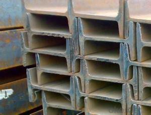


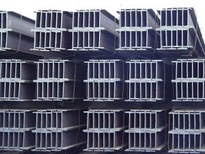
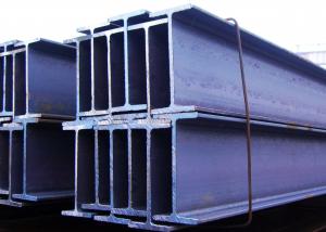
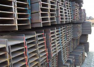
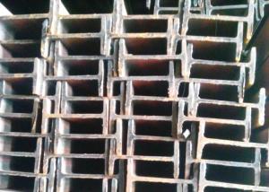
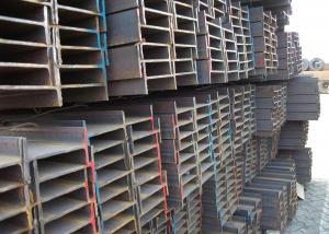
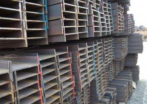
High Quality BS Standard Structure Steel I Beam Details
- Ref Price:
-

- Loading Port:
- Tianjin
- Payment Terms:
- TT OR LC
- Min Order Qty:
- 500 m.t.
- Supply Capability:
- 20000 m.t./month
OKorder Service Pledge
OKorder Financial Service
You Might Also Like
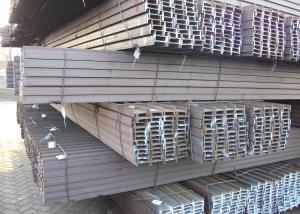
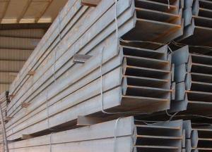
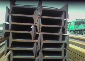
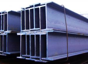
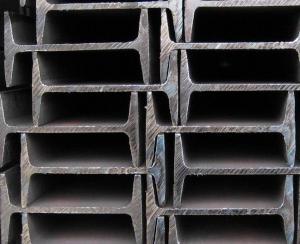
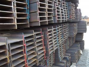
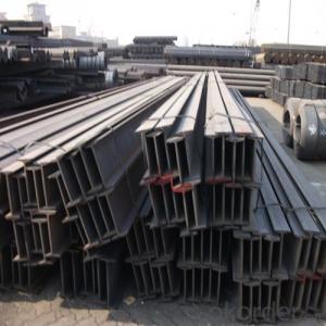
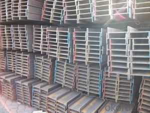
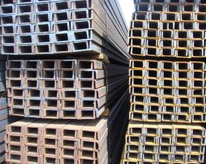
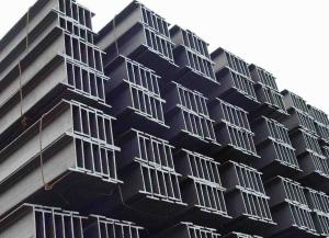
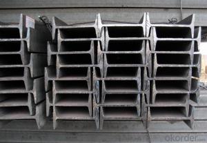
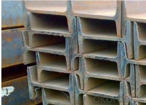
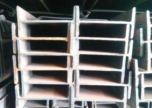
High Quality BS Standard Structure Steel I Beam Details
Commodity | High Quality BS Standard Structure Steel I Beam |
Standard | BS, JIS, ASTM, DIN, EN, GB/T 700-1988 |
Material | SS400, ST37-2 , A36, S235 JRG1, Q235, Q345 and more |
Chinese standard size | 100 x 68 x 4.5 to 630 x 180 x 17mm |
European standard size | 80 x 46 x 3.8 to 600 x 220 x 12mm |
Length | 6, 9, 12meter |
Packing | bundles, knitting bag or customized |
Application | construction |
Packaging Detail: in bundle and then load on 20 or 40 feet container or by bulk
Delivery Detail: within 25 days after receiving deposit or original L/C
Company Information
Our company is specialized in producing Hot Rolled Metal Structural Steel I Beam .With years of development, our company won the trust and excellen reputation of customers for the quality of our products and sincere service, as well as foreign users of the community.
Please contact me if you are interested in our products and I will try my best to offer you the best goods and service.
- Q:How do steel I-beams perform in corrosive environments?
- Steel I-beams typically perform well in corrosive environments due to their inherent resistance to corrosion. The high strength and durability of steel make it a preferred choice for construction materials, including I-beams, in areas where corrosion is a concern. However, the performance of steel I-beams in corrosive environments can vary depending on the specific conditions and the protection measures implemented. Steel I-beams are commonly manufactured with a protective coating, such as galvanization or painting, to enhance their resistance to corrosion. Galvanization involves applying a layer of zinc to the surface of the steel, creating a barrier that prevents direct contact between the steel and corrosive agents. This process significantly extends the lifespan of the I-beams in corrosive environments, making them highly reliable and long-lasting. The protective coating on steel I-beams not only acts as a physical barrier but also provides a sacrificial layer that corrodes instead of the steel itself. This sacrificial corrosion process further enhances the lifespan of the I-beams by sacrificing the coating while protecting the underlying steel structure. However, it is important to note that even with a protective coating, steel I-beams may still be susceptible to corrosion in highly aggressive environments, such as those with extremely high humidity, chemical exposure, or saltwater exposure. In such cases, additional corrosion protection measures, such as regular inspection, maintenance, and the use of specialized coatings, may be necessary to ensure optimal performance and longevity. Overall, steel I-beams are well-suited for corrosive environments due to their inherent resistance and the protective coatings applied during manufacturing. Proper maintenance and monitoring are crucial to ensure the continued performance of steel I-beams in corrosive environments and to identify and address any potential corrosion issues promptly.
- Q:How do you calculate the bending capacity of a steel I-beam?
- To calculate the bending capacity of a steel I-beam, you need to consider several factors such as the material properties of the steel, the shape and dimensions of the I-beam, and the applied load. Here is a step-by-step process to calculate the bending capacity: 1. Determine the material properties: Obtain the yield strength and modulus of elasticity of the steel being used. These values can typically be found in material specification documents or handbooks. 2. Identify the shape and dimensions of the I-beam: Measure the dimensions of the I-beam, including the flange width, flange thickness, web depth, and web thickness. The shape and dimensions of the I-beam will determine its section modulus (Z) and moment of inertia (I). 3. Calculate the section modulus (Z): The section modulus is a measure of a beam's resistance to bending. It can be calculated using the formula: Z = (b * h^2) / 6, where b is the flange width and h is the web depth. 4. Calculate the moment of inertia (I): The moment of inertia represents a beam's resistance to bending about its neutral axis. For an I-beam, the moment of inertia can be calculated using the formula: I = (b * h^3) / 12 + A * (d - h/2)^2, where A is the area of the flange and d is the total depth of the I-beam. 5. Determine the applied load: Identify the type and magnitude of the load that will be applied to the I-beam. This can be a uniformly distributed load (e.g., a floor load) or a concentrated load (e.g., a point load). 6. Calculate the bending stress: The bending stress, also known as the flexural stress, is calculated using the formula: σ = M / (Z * y), where M is the bending moment, Z is the section modulus, and y is the distance from the neutral axis to the extreme fiber. 7. Determine the maximum bending moment: Depending on the type of load applied, you will need to calculate the maximum bending moment using appropriate equations. For example, for a uniformly distributed load, the maximum bending moment can be calculated as M = (w * L^2) / 8, where w is the load per unit length and L is the span length. 8. Calculate the bending capacity: Finally, compare the calculated bending stress (σ) to the yield strength of the steel. If the bending stress is lower than the yield strength, the steel I-beam has sufficient bending capacity. However, if the bending stress exceeds the yield strength, the beam may experience plastic deformation or failure. It is important to note that this process provides an estimation of the bending capacity and should be used as a preliminary design tool. For accurate and precise calculations, it is recommended to consult with a structural engineer or refer to design codes and standards specific to your region.
- Q:How do steel I-beams perform in seismic zones?
- Due to their superior performance during earthquakes, steel I-beams are commonly utilized in seismic zones. The design and construction of steel I-beams offer several advantages that contribute to their exceptional resistance to seismic forces. To begin with, the high strength-to-weight ratio of steel I-beams enables them to withstand the lateral forces generated during earthquakes. The I-shaped cross-section efficiently distributes the seismic forces, reducing the likelihood of failure or collapse. Additionally, steel possesses ductility, meaning it can deform under stress without fracturing. This ductility aids in absorbing and dissipating the energy from seismic forces, minimizing potential damage. Furthermore, the seismic performance of steel I-beams can be enhanced through specific connections and details in their design. These connections are meticulously designed to provide flexibility and allow for relative movement between structural components. This flexibility aids in distributing the seismic forces and preventing concentrated stress points that could result in failure. Moreover, these connections ensure that the I-beams remain connected to the rest of the structure during earthquakes, establishing a continuous load path for the dissipation of seismic forces. Moreover, existing steel I-beam structures can be reinforced and retrofitted to improve their seismic performance. Additional bracing, cross-ties, or shear walls can be incorporated to enhance lateral stiffness and resistance to seismic forces. These retrofitting techniques significantly enhance the seismic resilience of steel I-beam structures. In conclusion, steel I-beams have demonstrated their effectiveness in seismic zones. Their high strength, ductility, and connection detailing position them as preferred structural materials for earthquake-resistant construction. However, it is crucial to ensure that the design and construction of steel I-beam structures adhere to local seismic codes and regulations to guarantee optimal performance and safety.
- Q:What are the different types of steel I-beam connections for cantilever structures?
- Some common types of steel I-beam connections for cantilever structures include welded connections, bolted connections, and moment connections.
- Q:What's the difference between plain I-beam and light I-beam? What is light I-beam?
- Ordinary steel processing is ordinary I-beam, Lu, magnesium and other light alloy processing is light construction steel.
- Q:What are the considerations for steel I-beam design in high-wind speed areas?
- When designing steel I-beams for high-wind speed areas, several considerations must be taken into account to ensure structural integrity and safety. These considerations include the following: 1. Wind load calculation: The first step is to accurately calculate the wind load that the I-beam will be subjected to. This involves considering the basic wind speed in the area, the exposure category of the building, and the importance factor of the structure. Wind tunnel testing and computer simulations may also be employed to determine the precise wind loads. 2. Material selection: Choosing the right grade and quality of steel is crucial in high-wind speed areas. High-strength steel is often preferred due to its superior tensile strength and ability to withstand higher wind loads. The steel should also be corrosion-resistant to prevent deterioration over time. 3. Beam size and shape: The size and shape of the I-beam are determined by the wind load calculations. The beam must be designed to resist the bending and shearing forces induced by the wind. Increasing the depth and flange width of the beam can enhance its stiffness and resistance to bending. 4. Connection design: The connections between the I-beam and other structural elements, such as columns or floor systems, must be carefully designed to ensure they can withstand the wind loads. Adequate moment and shear connections should be provided to transfer the wind forces between the components without compromising their integrity. 5. Bracing and lateral support: In high-wind speed areas, it is essential to incorporate bracing and lateral support systems to prevent the I-beam from buckling or deflecting excessively. Diagonal braces, cross-bracing, or moment frames can be used to provide stability and increase the overall rigidity of the structure. 6. Anchorage and foundation design: The foundation system must be designed to resist the uplift forces induced by the wind. Proper anchorage of the I-beam to the foundation is critical to prevent the structure from being lifted or displaced during high winds. Anchors, such as anchor bolts or dowels, should be appropriately sized and positioned to provide sufficient resistance. 7. Building codes and regulations: Compliance with local building codes and regulations is essential when designing steel I-beams in high-wind speed areas. These codes often specify minimum design requirements, construction techniques, and wind load factors that must be adhered to. Consulting with a structural engineer or a professional familiar with local codes is recommended. By considering these factors and following best practices, the design of steel I-beams in high-wind speed areas can be optimized for maximum safety and structural performance.
- Q:What are the common challenges in erecting steel I-beams on-site?
- When it comes to erecting steel I-beams on-site, there are numerous common challenges that can arise. One of the primary obstacles involves ensuring the proper alignment and positioning of the beams. Given their size and weight, maneuvering and lifting I-beams into place can be quite difficult. To ensure correct alignment and secure fit, precise measurements and meticulous planning are imperative. Another challenge lies in the requirement for specialized equipment and skilled labor. The process of erecting steel I-beams often necessitates the use of cranes, hoists, and other heavy machinery. These tools must be operated by trained professionals who possess a thorough understanding of the specific requirements and safety protocols associated with working with steel beams. The lack of access to such equipment and skilled labor can pose a significant hurdle during the erection process. Furthermore, the weight of steel I-beams can create challenges during transportation and installation. These beams typically exhibit considerable heaviness, necessitating careful coordination and planning to ensure that the site is adequately prepared to handle the weight. Additionally, the need for proper safety precautions, such as securely fastening the beams and ensuring proper bracing, adds complexity to the process. Moreover, weather conditions can also present challenges during the erection of steel I-beams. High winds, rain, or extreme temperatures can impact the stability of the beams and jeopardize the safety of the workers involved. It is crucial to closely monitor weather conditions and implement appropriate measures to mitigate any potential risks. Lastly, coordinating and communicating among the various stakeholders involved in the construction project can prove to be a challenge. Erecting steel I-beams often requires collaboration between architects, engineers, contractors, and subcontractors. Effective communication and coordination between these parties are pivotal in ensuring that the beams are installed correctly and meet the project's requirements. In conclusion, the challenges encountered while erecting steel I-beams on-site encompass alignment and positioning, the need for specialized equipment and skilled labor, the weight of the beams, weather conditions, and coordination among project stakeholders. Successfully addressing these challenges necessitates careful planning, expertise, and effective communication to guarantee a safe and successful installation process.
- Q:What are the potential drawbacks or limitations of using steel I-beams?
- Using steel I-beams in construction projects presents several potential drawbacks or limitations. To start, steel I-beams tend to be heavier and bulkier in comparison to other building materials like wood or concrete. This can make transportation and handling more challenging, necessitating specialized equipment and additional labor. In addition, steel is prone to corrosion if not adequately protected. Exposure to moisture, chemicals, and harsh weather conditions can cause rusting, compromising the structural integrity of the beams over time. Regular maintenance and protective coatings are necessary to prevent corrosion and ensure the longevity of the steel I-beams. Another limitation is the cost associated with steel I-beams. Steel is an expensive material, and the fabrication and installation of I-beams can significantly inflate the overall construction budget. This can pose a challenge for projects with tight financial constraints. Moreover, steel I-beams have limitations in terms of design flexibility. Although they offer excellent strength and load-bearing capabilities, their shape and dimensions are predetermined. This restricts the architectural possibilities and can curtail the creativity and versatility of the building design. Lastly, steel I-beams have relatively poor thermal insulation properties. They conduct heat more efficiently than materials like wood or concrete, meaning they can contribute to heat loss or gain in a building. Additional insulation measures must be taken to ensure energy efficiency and maintain comfortable indoor temperatures. In conclusion, while steel I-beams are widely used and offer numerous advantages in construction, it is important to carefully consider their potential drawbacks such as weight, susceptibility to corrosion, cost, limited design flexibility, and thermal insulation limitations when selecting the appropriate building material for a specific project.
- Q:How is a steel I-beam manufactured?
- A steel I-beam is manufactured through a process called hot rolling, where a long steel billet is heated until it becomes malleable. It is then passed through a series of rollers to shape it into the desired I-beam profile. Once the beam is formed, it undergoes cooling and straightening processes to ensure its structural integrity. Finally, it is cut into the required lengths and may undergo additional treatments such as painting or galvanizing before being ready for use in construction projects.
- Q:Specification for I-beam used in interlayer decoration
- The root of the ordinary beam wing edge and light I-beam to the edge of the thinning, have a certain angle, the ordinary beam and light I-beam model is the digital Arabia with its waist high cm number to represent, web and flange thickness and flange width of different specifications (H) with high waist leg width (x B) * (d) no waist thick number said, such as "general 160 x 88 x 6", that is 160 mm high waist, leg width is 88 mm, 6 mm thick waist for ordinary i-beam. [light industrial 160 * 81 * 5), which means that the waist height is 160 mm, the width of the leg is 81 mm, and the thickness of the waist is 5 mm. Ordinary I-beam specifications are also available models, showing the type of waist high number of centimeters, such as general 16#. I-beam with the same waist height,
1. Manufacturer Overview |
|
|---|---|
| Location | |
| Year Established | |
| Annual Output Value | |
| Main Markets | |
| Company Certifications | |
2. Manufacturer Certificates |
|
|---|---|
| a) Certification Name | |
| Range | |
| Reference | |
| Validity Period | |
3. Manufacturer Capability |
|
|---|---|
| a)Trade Capacity | |
| Nearest Port | |
| Export Percentage | |
| No.of Employees in Trade Department | |
| Language Spoken: | |
| b)Factory Information | |
| Factory Size: | |
| No. of Production Lines | |
| Contract Manufacturing | |
| Product Price Range | |
Send your message to us
High Quality BS Standard Structure Steel I Beam Details
- Ref Price:
-
- Loading Port:
- Tianjin
- Payment Terms:
- TT OR LC
- Min Order Qty:
- 500 m.t.
- Supply Capability:
- 20000 m.t./month
OKorder Service Pledge
OKorder Financial Service
Similar products
New products
Hot products
Related keywords

