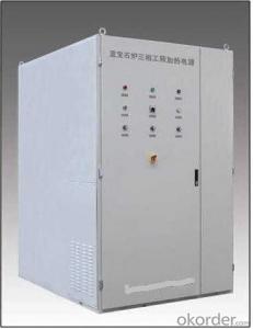
Low Frequency Electronic Transformer
- Ref Price:
-

- Loading Port:
- China Main Port
- Payment Terms:
- TT or LC
- Min Order Qty:
- 800 Pieces pc
- Supply Capability:
- 10000 Pieces per Month pc/month
OKorder Service Pledge
OKorder Financial Service
You Might Also Like
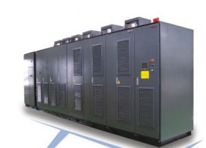
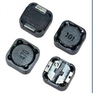
*Electric power Inductor
*High power storage
*Easy insertion,low price
*Used in various electronic and industry products
Our products have gained the international certifications, such as CQC, CE, RoHS, UL and so on, from internationally powerful authorities. We have got ISO9001 certificate. We promise to offer the best products to our clients.We look forward to cooperating with all friends for more mutual benefits. |
- Q:An ac generator has a frequency of 5.0 kHz and a voltage of 22 V. When an inductor is conencted between the terminals of this generator, the current in the inductor is 10 mA. What is the inductance of the inductor?
- The reactance is 22/10ma 2200 ohms X? 2πfL 2200 2π(5000)L L 0.070 H or 70 mH .
- Q:If the 30mH inductor and the 0.05?F capacitor were used to produce a sine wave from the square wave output. What harmonics of the square wave would be produced across the inductor?
- Without knowing the square wave frequency and how the inductor and capacitor are connected (series or parallel), this question can't be answered. Assuming the sine wave output is taken across the capacitor and that the inductor and capacitor are in series, all odd harmonic of the square waves fundamental frequency will appear across the inductor.
- Q:A 150 Omega resistor is connected in series with a 0.250-H inductor. The voltage across the resistor is v_R(3.80 V) *[cos(720*rad/ s)*t]Derive an expression for the circuit current. and Derive an expression for the voltage v_L across the inductor.I got by the equation I v/R.0253A*cos((720*rad/s)*t)and for the other i got by the equation v_LL* (di/dt) -(4.55*V)*sin((720 rad/s)*t)
- Not quite answering, but just pointing out that your sin and cos expressions could be written as (ex) sin[(720 rad/s) * t] Now when you substitute a value for t, the units inside the brackets become radians after cancellation and then all is well in the ups and downs. I think you have answered the question well, as long as your calculus is done correctly.
- Q:If the current through an inductor were doubled, the energy stored in the inductor would be1. doubled.2. the same.3. halved.4. quartered.5. quadrupled.
- E 0.5 L i^2 the energy would be increased by 2^2 or quadrupled answer 5
- Q:Current through an inductor is turned on at time t0, as shown in the figure. Vscos(200*pi*t). Calculate the energy delivered to the inductor at t21 ms.Here's the figure:
- I(1/L)*integral(V dt). Note that you need to consider the initial conditions, when finding the solution. Once you get the solution, just plutg in t21ms.
- Q:If ig(t) 0.5 cos 2000t A, find the average power absorbed by each element ((a) 130-Ω resistor, (b) 40-Ω resistor, (c) source, (d) inductor, (e) capacitor) in the circuit in the figure below.
- Let's just go through it the straight way. You know, from your source, that: ? ? ? ? ω 2000 ? ? ? ? Ip ?A, ∴ Irms Ip ? (√2) You can compute the reactance of your capacitor (C12.5μF) and inductor (L60mH) as: ? ? ? ? XC 1 ? (ω?C) 40?, ∴ Z?C -40j ? ? ? ? XL ω?L 120?, ∴ Z?L 120j Let's say that: ? ? ? ? R? 130? ? ? ? ? R? 40? You have two parallel legs, each with a series pair of devices. The total impedance is in the capacitive leg is: ? ? ? ? Z? R? + Z?C 130 - 40j, ∴ |Z?| 10√185 In the inductive leg it is: ? ? ? ? Z? R? + Z?L 40 + 120j, ∴ |Z?| 40√10 So the total parallel impedance of these two legs is: ? ? ? ? Ztot Z??Z? ? (Z? + Z?) 200?(141 + 79j) ? 353 ? ? ? ? ∴ |Ztot| ≈ 91.57112 You know that: ? ? ? ? Vrms Irms ? |Ztot| ? ? ? ? Irms? Irms ? |Ztot| / |Z?| ? ? ? ? Irms? Irms ? |Ztot| / |Z?| ? ? ? ? P? Irms???R? (Irms ? |Ztot| / |Z?|)? ? R? 7??????? W ≈ 7.365 W ? ? ? ? P? Irms???R? (Irms ? |Ztot| / |Z?|)? ? R? 2??????? W ≈ 2.620 W ? ? ? ? Ptot P? + P? 9??????? W ≈ 9.986 W Real power isn't dissipated in ideal capacitors or inductors, so (a) ≈ 7.365 W, (b) ≈ 2.620 W, (c) ≈ 9.986 W, (d) 0 W, and (e) 0 W. Since the problem you show doesn't illustrate VAR units on it, I don't think (d) and (e) should use reactive power. ? ? ? ? P? Irms???R? (Irms ? |Ztot| / |Z?|)? ? R? 7??????? W ≈ 7.365 W ? ? ? ? P? Irms???R? (Irms ? |Ztot| / |Z?|)? ? R? 2??????? W ≈ 2.620 W The above was validated with Spice.
- Q:I read in an article on wikipedia entitled pulsed power that it is possible to store and release energy by using inductors to accomplish a process called energy compression. How would an inductor be used in such a case? In my application, if I had a input of 20mV at 1.5mA for 1.25 seconds that I put into (accumulated over the 1.25 seconds) the inductor and wanted to release all of that energy in 0.1 or 0.2 seconds, then how could I calculate my output voltage and current values for my output over the 0.1 or 0.2 seconds? It would be greatly appreciated if you could demonstrate your calculations using an applicable formula, just to make sure I understand the math correctly. Thanks!!
- a million) 3 pulse rectifier makes use of purely 3 diodes (as in a million/2 wave rectifiers), or 3 SCR for administration and 3 diodes just to furnish the returning direction. while in 6 pulse rectifiers, we use 6 diodes or 6 SCRs, all for use for controlling objective (comparable as finished wave rectifier). 2) 3 pulse rectifier delivers a extreme ripple voltage with fairly decrease frequency. subsequently, the extreme means and extreme fee ripple rejection capacitors are mandatory. yet in 6 pulse rectifiers, the ripple is of extreme frequency, subsequently much less fee capacitors are mandatory, lowering the cost. 3) Ripple is barely 14% in 6 pulse, subsequently, the performance is extreme in 6 pulse than in 3 pulse. 4) The output DC voltage in 3 pulse association may be a million.40-one instances the voltage score of transformer, yet in 6 pulse, it may circulate upto 2.40 5 instances. subsequently, low voltage score transformer will artwork for it, back, lowering the cost.
- Q:Ex. Negatively charged vinyl strip touches sphere of an electroscope. What happens to the leaves and positions of charges?
- Then, positive charges interact with the negatively charged inductor Good luck!
- Q:Describe what happens to the impedance of an inductor at very high frequencies qualitatively.thanks in advance!
- I'm only answering this because it's a very important concept that isn't always clearly stated in the books. DC conditions: Capacitors become open circuits. Inductors become short circuits. AC conditions: Capacitors become resistors that decrease in resistance aka impedance as the frequency increases. Inductors become resistors that increase in resistance aka impedance as the frequency increases. DC is like a frequency of 0Hz so you can see why the DC conditions are as they are.
- Q:i am making an Am transmitter and i need a 5 mH inductor for the 1MHz oscillator.
- That is a very big coil to make yourself. It is too big to resonate at 1 MHz. About 70 microhenries would resonate with 360 pF at that frequency. It would be easier to get an oscillator coil from an old transistor radio and put about 300 pF across it. If fact it already covers about 1 MHz to 2 MHz with the existing tuning capacitor. If you want to make the coil yourself, use Wheeler's formula: The classic formula for single-layer inductance (air core) is called Wheeler's formula, which dates back to the radio days of the 1920s: L(N^2 times R^2) / ( 9 *R + 10 *H) where: L inductance in micro-Henries N number of turns of wire R radius of coil in inches H height of coil in inches In most countries, transmitters are not permitted on any frequency unless authorised, and especially not in the middle of the AM broadcast band.
1. Manufacturer Overview |
|
|---|---|
| Location | Shenzhen, Guangdong, China (Mainland) |
| Year Established | 2006 |
| Annual Output Value | US$2.5 Million - US$5 Million |
| Main Markets | North America; South America; Eastern Europe; Southeast Asia; Africa; Oceania; Mid East; Eastern Asia; Western Europe; Central America; Northern Europe; Southern Europe; South Asia; Domestic Market |
| Company Certifications | CE Certificates |
2. Manufacturer Certificates |
|
|---|---|
| a) Certification Name | |
| Range | |
| Reference | |
| Validity Period | |
3. Manufacturer Capability |
|
|---|---|
| a)Trade Capacity | |
| Nearest Port | Shekou,Yantian |
| Export Percentage | 51% - 60% |
| No.of Employees in Trade Department | 3-5 People |
| Language Spoken: | English, Chinese |
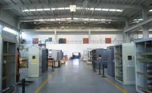
| b)Factory Information | |
| Factory Size: | 3,000-5,000 square meters |
| No. of Production Lines | 9 |
| Contract Manufacturing | OEM Service Offered Design Service Offered Buyer Label Offered |
| Product Price Range | Average |
Send your message to us
Low Frequency Electronic Transformer
- Ref Price:
-
- Loading Port:
- China Main Port
- Payment Terms:
- TT or LC
- Min Order Qty:
- 800 Pieces pc
- Supply Capability:
- 10000 Pieces per Month pc/month
OKorder Service Pledge
OKorder Financial Service
Similar products


New products


Hot products

Hot Searches
Related keywords

