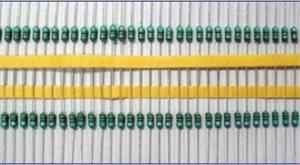

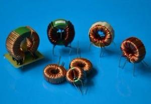
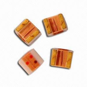
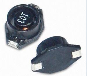
Color Loop Inductor
- Ref Price:
-

- Loading Port:
- China Main Port
- Payment Terms:
- TT or LC
- Min Order Qty:
- 1000 Pieces pc
- Supply Capability:
- 10000 Pieces per Week pc/month
OKorder Service Pledge
Quality Product, Order Online Tracking, Timely Delivery
OKorder Financial Service
Credit Rating, Credit Services, Credit Purchasing
You Might Also Like

1.Qualified material competative price
2.small loss
3.usage:instrutment phase:single
4.coil structure:axial
5.core dimension:adjustable by clients
6.size:follow according client's requirement
7.Remark:we can produce it according client's requirement
Our products have gained the international certifications, such as CQC, CE, RoHS, UL and so on, from internationally powerful authorities. We have got ISO9001 certificate. We promise to offer the best products to our clients. We look forward to cooperating with all friends for more mutual benefits.
- Q:An RL circuit consists of two inductors of self-inductance L1 10.00 H and L2 4.00 H connected in parallel to each other, and connected in series to a resistor of 6.00 ? and a battery of 4.00 V (See figure). Assume that the inductors have no mutual inductance. When the battery is suddenly connected what is the inital rate of change of the current in inductor L1?Figure:
- Initially no current flows in L1 or L2, so the voltage drop across R 0 and thus 4 V is applied to L1 and L2. Use the formula V LdI/dt to find dI1/dt and dI2/dt. P.S. You did a bad copy of the imageshack page URL. What you posted actually ends with just as it appears, which is not a URL. That's because you used a simple copy command (ctrl-C or whatever) instead of Copy Shortcut. I'm assuming you have R + (L1 || L2), where + means 'in series with' and || means 'in parallel with'. EDIT: OK, got your URL and it's the way I assumed it was and fits your description.
- Q:A coil has an inductance of 0.80 H and a resistance of 41 . The coil is connected to a 5.0 V ideal battery. (a) When the current reaches half its maximum value, at what rate is magnetic energy being stored in the inductor? (b) When the current reaches half its maximum value, at what rate is energy being dissipated? (c) When the current reaches half its maximum value, what is the total power that the battery supplies?
- An inductor might no longer likely keep magnectic capability. It converts electric powered capability flowing with the aid of it to magnectic capability. If the electricity flow is stopped, the magnectic field colapses (like Jis4Jenius Jerald pronounced above). it extremely is termed an inductor using fact a changing magnetic field around the cord (or coil) induces electricity into it.
- Q:A 12.6 V battery is in series with a 30.0 mH inductor and 0.150 ohm resistor connected through a switch. When the switch is closed at t o, find time constant of the circuit( ans: 0.2 s) Find the current after 1 time constant has elapsed ( ans: 53.1 A) Find the voltage drop across R after t0 and after one time constant ( ans: 0 volts and 7.97 V ) find rate of change of current after one time constant( ans: 150 A/s)I have the answers, but I need a step by step? I'd appreciate any help.
- Let V_s the voltage of the battery 12.6 V Let i the current through the series circuit Let R the resistance of the resistor 0.150 Ω Let L the inductance of the inductor 0.03 H Let V_r the voltage across the resistor (i)R Let V_l the voltage across the inductor L(di/dt) The source voltage must equal the sum of the voltages across the components: V_s V_r + V_l 12.6 V (i)R + L(di/dt) di/dt + (i)(R/L) (12.6 V)/L The integrating factor for this is e^{∫ (R/L)dt} e^{(R/L)t} e^{(R/L)t}di/dt + e^{(R/L)t}(i)(R/L) e^{(R/L)t}(12.6 V)/L The left side integrates as the reverse of the product rule and the right side integrates with the reciprocal of the coefficient with a constant, C: e^{(R/L)t}(i) e^{(R/L)t}(12.6 V)/R + C Multiply both sides by e^{-(R/L)t}: (i) (12.6 V)/R + Ce^{-(R/L)t} i (12.6 V)/0.150 Ω + Ce^{-(R/L)t} i 84 A + Ce^{-(R/L)t} We find the value of C by knowing that i 0 at t 0 0 84 A + Ce^0 C - 84 A i (84 A)(1 - e^{-(R/L)t}) To find the time constant set (R/L)t 1: t L/R 0.03/0.150 0.2 s One time constant means that -(R/L)t -1 i (84 A)(1 - e^-1) ≈ 53.1 A The current is 0 at t 0 so V_r R(0) 0 The current is 53.1 A at t 0.2 s so V_r (0.150 Ω)(53.1 A) ≈ 7.97 V The charge rate is di/dt and we have an equation involving that: di/dt + (i)(R/L) (12.6 V)/L Solve for di/dt: di/dt (12.6 V)/L - (i)(R/L) di/dt 12.6 V/0.03 H - (53.1 A)(0.150 Ω/0.03 H) di/dt 154.5 A/s
- Q:A homework question for my Electromagnetic Fields and Waves course asks, How would you build a 0.1H inductor? I am extremely stuck! I have researched and tried to figure this out but I am having no luck. My classmates are having trouble as well. Please help!
- Let me split your question into two parts. How do you build an inductor? How to make it 0.1H? Building an inductor is very simple. Wind a few turns of wire and you have an air cored inductor. That means, you basically need two things to build an inductor. A conductor having a certain number of turns and a core. The core can be air, silicon steel, nickel, soft ferrite, hard ferrite, powdered iron How to make it 0.1 Henry (100mH)? So an inductor has a certain inductance. The inductance depends on the number of turns and the material of the core. Apart from the two, you need to know the following factors: 1. Current through the conductor, 2. Type, size, area and permeability of the core 3. The frequency of operation. The current is important, because it should not saturate the core. Read info regarding the B/H curve. To keep it simple, for a single layer AIR CORED INDUCTOR the formula is: L ((r^2)(N^2)) / (9r+10l) where L is inductance in microhenrys, r is radius of coil in inches, l is the length of coil in inches, and N is the number of turns in the coil.
- Q:How do I figure out inductor equivalence when you have a series parallel combination inductor circuit
- The rules for combining inductors are the same as those for resistors. In series, L L1 + L2 In parallel, 1/L 1/L1 + 1/L2
- Q:Building a BFO metal detectorReference coils calls for,AWG #30dimensions: 50 mm height x .5 mm width120 turnsI'll be using AWG #24. However, AWG #24 is .5 mm in diameter. If you do the math, that's120 turns x .5 mm 60 mmSo my coil will be 60 mm. THAT'S NOT WHAT THE ENGINEER CALLS FOR. I'm 10 mm too long, therefore I have an extra 20 winds (10 mm of 24 awg 20 winds)CAN I OVERLAP?Problem is the reference coil (this coil) is fitted into a water fitting. The water fitting is threaded on the outside fitted with a nut. When you move the nut up down the water fitting, it changes the frequencyWon't this be an issue?THanks
- The final inductance increases a little bit by overlap winding.
- Q:If the current for a closed switch is increasing exponentially (inversely) across an inductor, what is the voltage doing (decreasing the time constant multiple of an inverse exponential?)
- If the inductor is a real inductor, with series resistance, not a superconducting or mathematically ideal, then a constant voltage connected across it initially has the current limited completely by the inductance. The formula for the relation between inductor current and voltage is that the rate of change of current is proportional to the voltage across the inductor. So, at the beginning, the current ramps linearly up from zero after voltage is connected across the inductor. But as soon as there is current, there is also voltage lost across the internal resistance in the wire that makes up the inductor. So as the current rises, there is a rising loss of voltage that remains across the inductance, since some of the total voltage is lost across the resistance of the inductor. This falling effective voltage across the inductance causes the rate of rise of the current to fall the current rises at a lower and lower rate.) Eventually, the current will have risen high enough that the resistance uses up all of the voltage with zero left to drive a current increase across the inductance and the current reaches an ultimate value of V/R amps. The series resistor inductor combination therefore has a current time constant under constant total voltage. When the voltage has been on for L/R seconds (with L being the inductance in henries and R, the resistance in ohms), the current will have risen to 62% of the ultimate (steady state current. In another L/R seconds, the current will reach 62% of what is left of the way to that ultimate current, etc. The link I included, below has the actual exponential formula for this rising current, that is difficult to write with text only. -- Regards, John Popelish
- Q:Calculate the impedance of the circuit if the source frequency is 60 Hz and when it is 6.9*10^4 Hz
- R30 x 10^3 ohms L80 x 10^6 henry f60hz omega2(pi)f120(pi) impedence by inductoromega*L impedence by resistorR total impedenceroot of(R(square) + Omega*L(square))
- Q:At what frequency f is the peak current 60 mA ? I found this answer to be 3.6x10^4 HzWhat is the instantaneous value of the emf at the instant when iLIL?I cannot figure this second part out. Please explain clearly, Thank you!
- XL 5.7V/.06A 95 Ohms XL 2pi fL 95 Ohms 2pi f(.000420) f 95/(.002638938) 35,9999 Hz ~ 36 kHz I'm not familiar with the difference in the two symbols iL and IL. Let us know and some of us will be able to answer the second part of your question. The inductor current (iL) equals the total current in amplitude and phase at all times. The output emf of the generator leads (iL) by 90 degrees. VL is in phase with the output emf of the generator. But I don't know what the symbol (IL) stands for.
- Q:A 4.40 mH inductor has an rms voltage of 24.9 V across it at a frequency of 230.I just can't find a formula that relates these things, yet my homework is asking it. WTF!!? help random internet people.
- The peak current is when the voltage is at it's peak divided by the reactance. The peak sinusodial voltage is 29.4V * SQRT (2) 29.4V * 1.414 41.5779 V (peak) The inductive reactance is 2 * pi * Freq * L 2 * 3.1415 * 230 * 4.4 * 10E-3 6.3586 ohms Using ohms law V / R I ; 41.5779 V / 6.3586 ohms 6.5389 Amps (peak) To find the RMS voltage multiply by the square root of 2 divided by 2 or 0.707 So 6.5389 Amps * 0.707 4.6237 Amps This is also the RMS Voltage divided by the inductive reactance ! :-b
Our goods sell very well and gain a good reputation from the clients with our production scale, environmentally friendly products, excellent product quality, first-class enterprise management, the most competitive price and perfect service.Our products have gained the international certifications, such as CQC, CE, RoHS, UL and so on.
1. Manufacturer Overview |
|
|---|---|
| Location | Shenzhen, Guangdong, China (Mainland) |
| Year Established | 2006 |
| Annual Output Value | US$2.5 Million - US$5 Million |
| Main Markets | North America; South America; Eastern Europe; Southeast Asia; Africa; Oceania; Mid East; Eastern Asia; Western Europe; Central America; Northern Europe; Southern Europe; South Asia; Domestic Market |
| Company Certifications | CE Certificates |
2. Manufacturer Certificates |
|
|---|---|
| a) Certification Name | |
| Range | |
| Reference | |
| Validity Period | |
3. Manufacturer Capability |
|
|---|---|
| a)Trade Capacity | |
| Nearest Port | Shekou,Yantian |
| Export Percentage | 51% - 60% |
| No.of Employees in Trade Department | 3-5 People |
| Language Spoken: | English, Chinese |
| b)Factory Information | |
| Factory Size: | 3,000-5,000 square meters |
| No. of Production Lines | 9 |
| Contract Manufacturing | OEM Service Offered Design Service Offered Buyer Label Offered |
| Product Price Range | Average |
Send your message to us
Color Loop Inductor
- Ref Price:
-
- Loading Port:
- China Main Port
- Payment Terms:
- TT or LC
- Min Order Qty:
- 1000 Pieces pc
- Supply Capability:
- 10000 Pieces per Week pc/month
OKorder Service Pledge
Quality Product, Order Online Tracking, Timely Delivery
OKorder Financial Service
Credit Rating, Credit Services, Credit Purchasing
Similar products


New products

Hot products
Hot Searches

